
Maintaining desirable performance of optical emitters over temperature variations

a technology of optical emitters and temperature variations, applied in the direction of semiconductor laser arrangements, electromagnetic transmission, semiconductor lasers, etc., can solve the problem of inaccurate temperature compensation schemes using thermistors, and achieve the effect of accurately compensating changes in the performance of lasers over temperature fluctuations

Inactive Publication Date: 2005-03-01
II VI DELAWARE INC
View PDF2 Cites 53 Cited by
  • Summary
  • Abstract
  • Description
  • Claims
  • Application Information

AI Technical Summary

Benefits of technology

This patent describes how a controller determines the optimal settings for supplying power to a laser during use based on its internal temperature measurements. By adjusting these settings, the controler ensures accurate compensation for any changes in the laser's performance due to heat variations.

Problems solved by technology

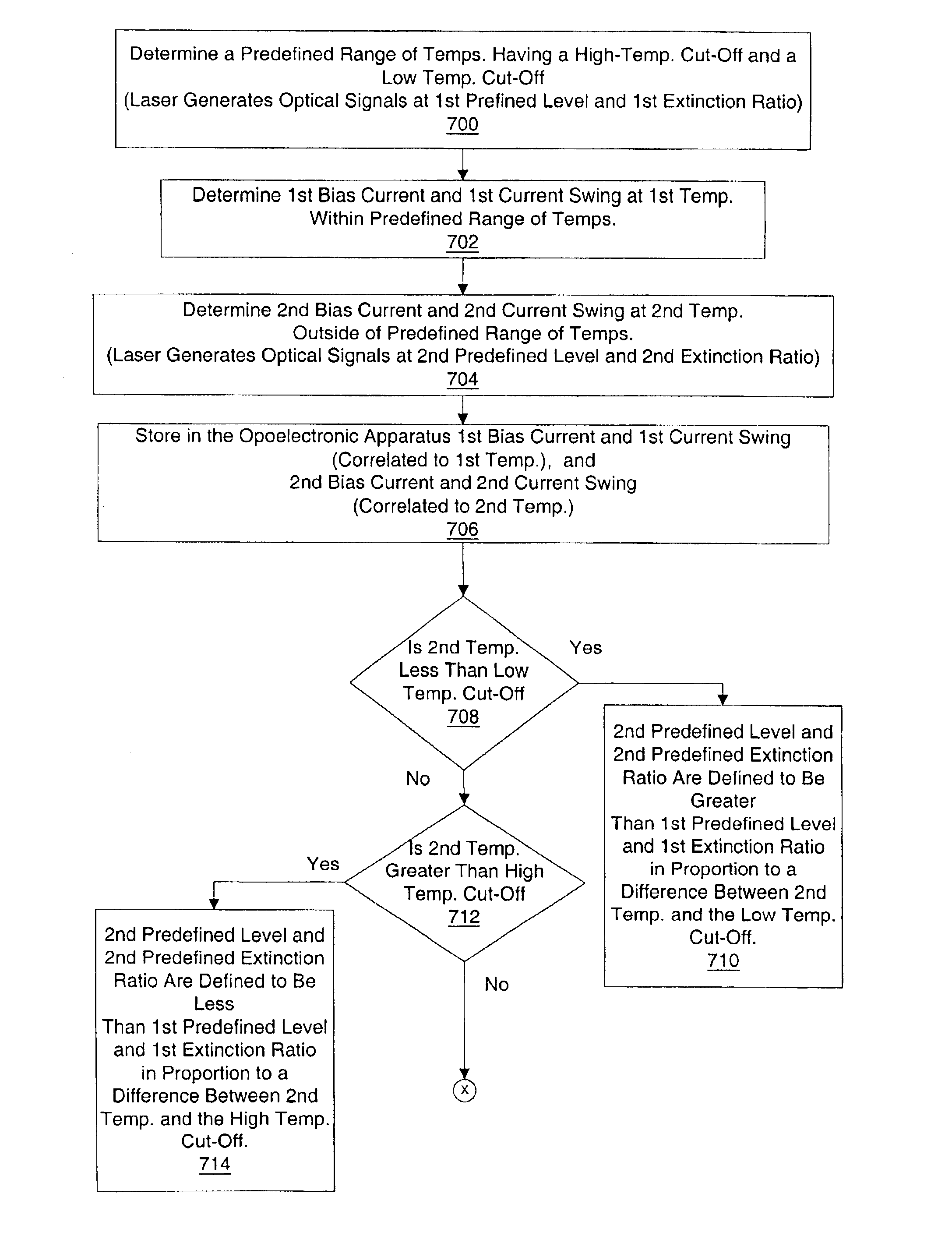
The technical problem addressed in this patent is the need for a method to maintain consistent performance of optical emitters, such as lasers and LEDs, over temperature variations. The prior art method using thermistors is inaccurate due to variations in thermistor characteristics and laser characteristics. The present invention provides a method to compensate for changes in optical power and extinction ratio of the laser over temperature variations, optimizing fiber optic transmitter eye quality. The method uses a calibration process to sample the performance of the laser at different temperatures and record the appropriate control values for the DC bias current and AC current swing used at each temperature. The controller uses these recorded control values to determine the appropriate control signals for the laser driver circuit and compensate for changes in laser performance over temperature fluctuations.

Method used


Image

  • Maintaining desirable performance of optical emitters over temperature variations
  • Maintaining desirable performance of optical emitters over temperature variations
  • Maintaining desirable performance of optical emitters over temperature variations

Examples


Embodiment Construction

Preferred embodiments of the invention are described below. In the interest of clarity, not all features of an actual implementation are described. It will be appreciated that in the development of any such embodiment, numerous implementation-specific decisions must be made to achieve the developers' specific goals, such as compliance with system-related and business-related constraints, which will vary from one implementation to another. Moreover, it will be appreciated that such a development effort might be complex and time-consuming, but would nevertheless be a routine undertaking for those of ordinary skill in the art having the benefit of this disclosure.

Fiber Optic Transceiver Components

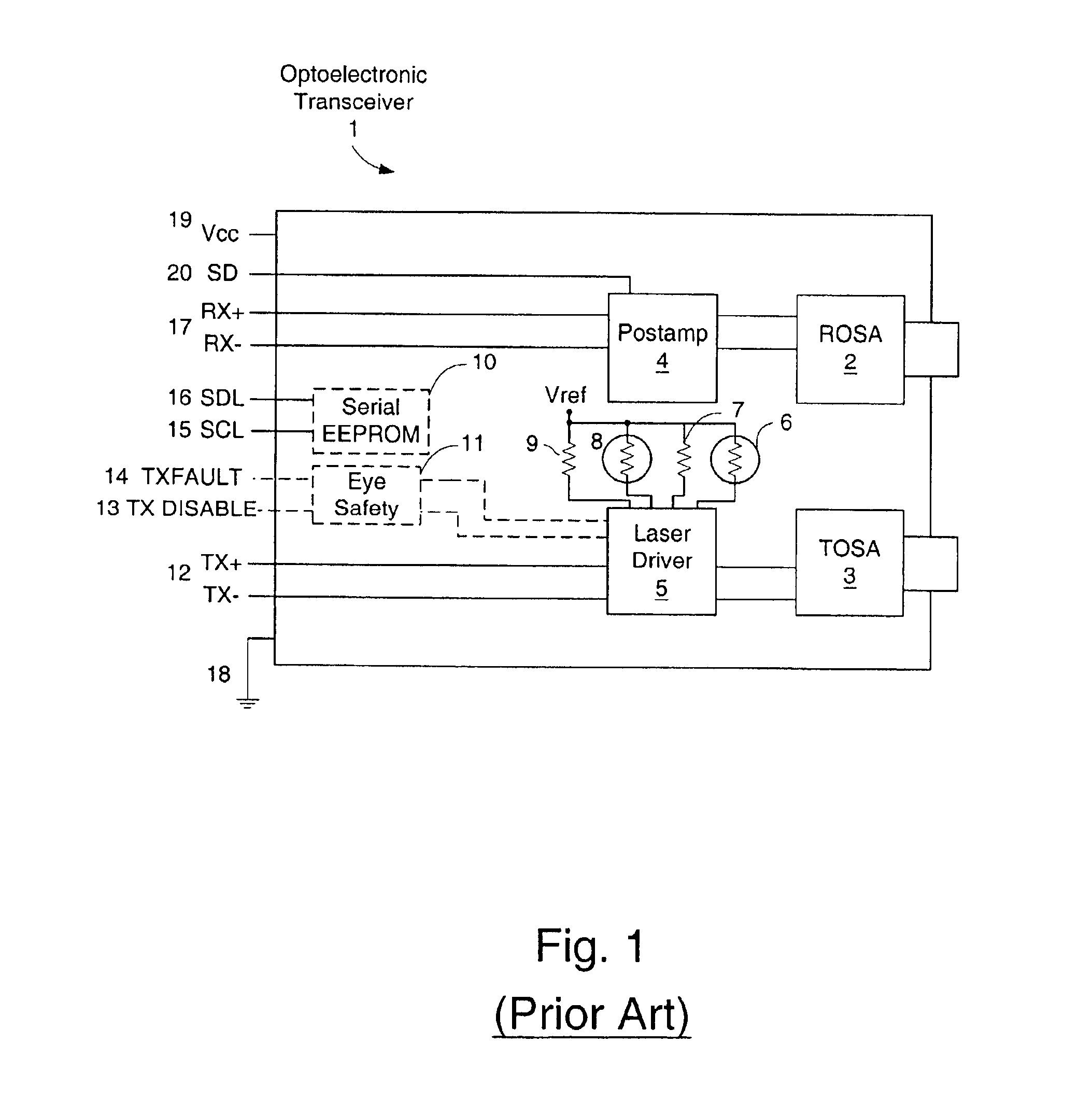
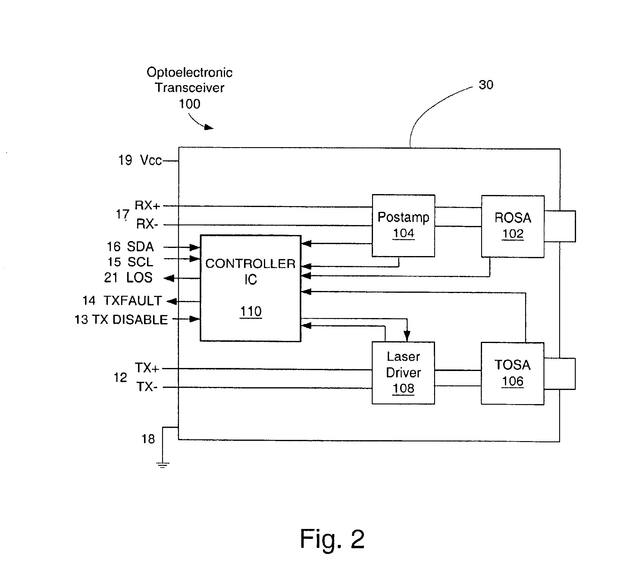
A transceiver 100 in which embodiments of the present invention may be practiced is shown in FIGS. 2 and 3. The transceiver 100 contains a Receiver Optical Subassembly (ROSA) 102 and Transmitter Optical Subassembly (TOSA) 106 along with associated post-amplifier 104 and laser driver 108 integr...


PUM


Abstract

A method of maintaining desirable optical performance of optical emitters over temperature variations is disclosed. The optical performance of an optical emitter in terms of power, extinction ratio, jitter, mask margin and general fiber optic transmitter eye quality can be maintained by the present invention over a wide range of temperatures. Advantageously, the present invention enables the use of inexpensive optical emitters in optoelectronic transceivers and optoelectronic transmitters.

Description


Claims


Application Information

Patent Timeline
Owner II VI DELAWARE INC
Learn More