Retaining system for a rotor of a dynamoelectric machine

a technology of dynamoelectric machines and retaining systems, which is applied in the direction of dynamoelectric machines, electrical devices, windings, etc., can solve the problems of high cost, achieve the effect of providing both the strength and rigidity necessary, and reducing the number of cylinders

Inactive Publication Date: 2005-03-08
GENERAL ELECTRIC CO
View PDF10 Cites 18 Cited by
  • Summary
  • Abstract
  • Description
  • Claims
  • Application Information

AI Technical Summary

Benefits of technology

A notable aspect of the present invention is that the retaining system has a relatively uncomplicated construction, yet provides both the strength and rigidity necessary to restrain the end turns of the field windings, even when subjected to high centrifugal forces generated when the rotor spins at high speeds. If the retainer member is formed of a composite material instead of a high-strength, nonmagnetic steel such as 1818, the invention avoids the disadvantages associated with using 1818 steel, such as limited sources, long delivery cycles, and the high costs associated therewith. The relatively low density possible for a retainer member formed of a composite material permits the use of rotors having larger diameters and higher spin speeds than is practical when using the more dense 1818 steel.

Problems solved by technology

Sources of 1818 steel are limited and delivery cycles can be long, resulting in high costs.
Furthermore, separation of the ring 16 and rotor 10 becomes a design challenge at higher rotor speeds.

Method used


Image

  • Retaining system for a rotor of a dynamoelectric machine
  • Retaining system for a rotor of a dynamoelectric machine
  • Retaining system for a rotor of a dynamoelectric machine

Examples


Embodiment Construction

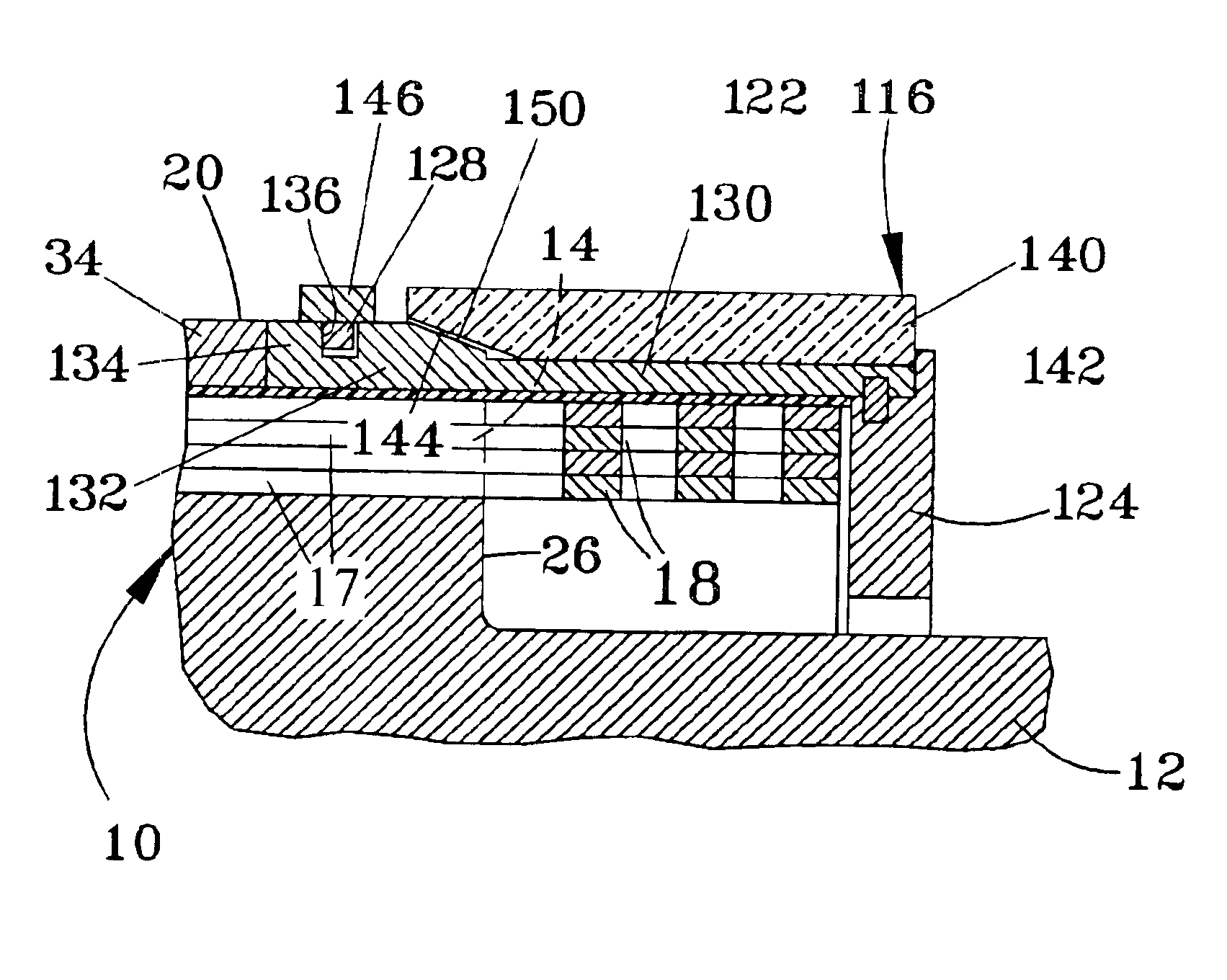
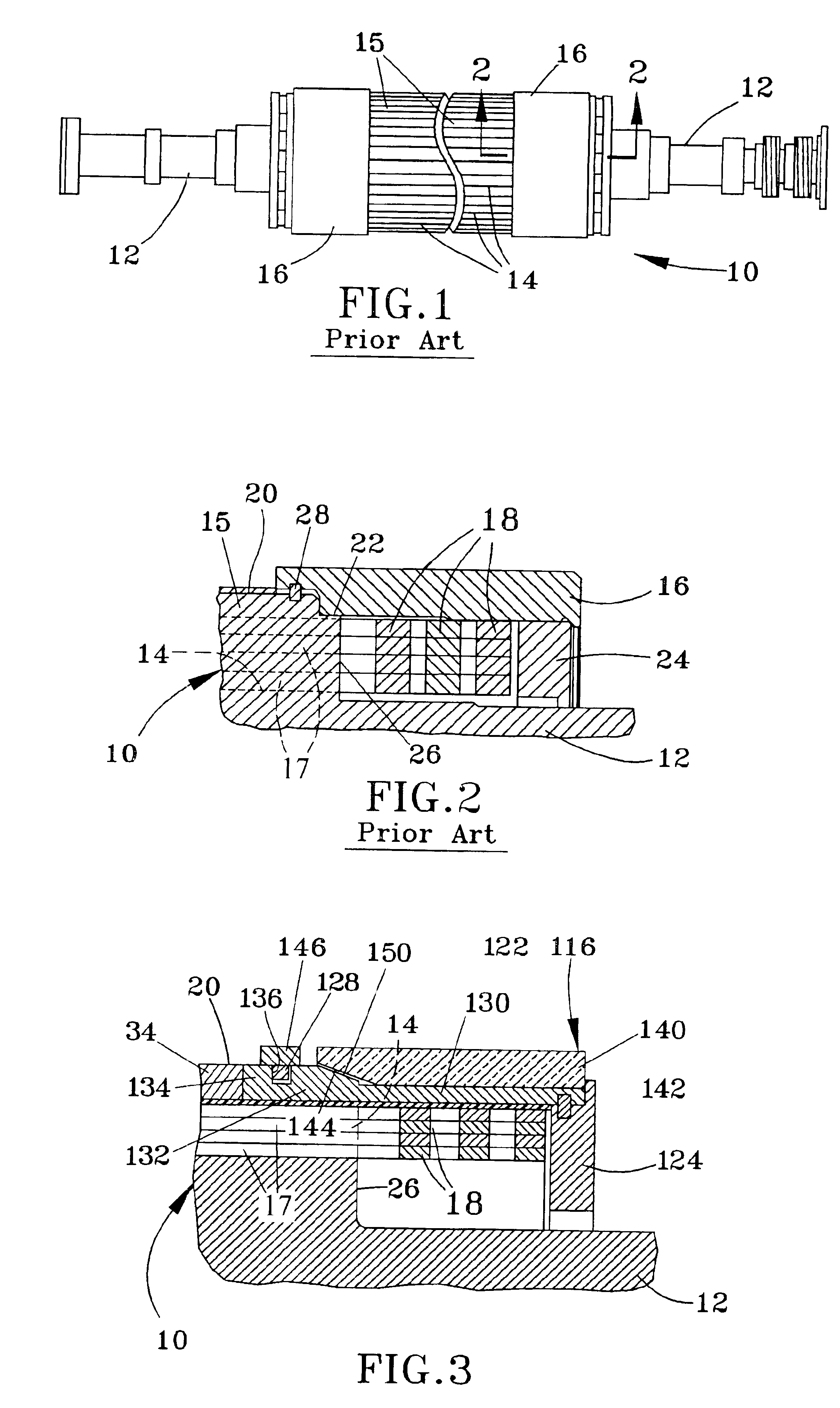
FIGS. 3 and 4 represent partial sectional views of a rotor 10 similar to the rotor 10 of FIGS. 1 and 2, such that the same reference numbers will be used to identify the same or equivalent features of the rotors 10. As such, the rotor 10 is of the type used in power generation plants that serve as primary suppliers of high-voltage alternating current to a distribution or transmission network, though the rotor 10 could be used in other applications.

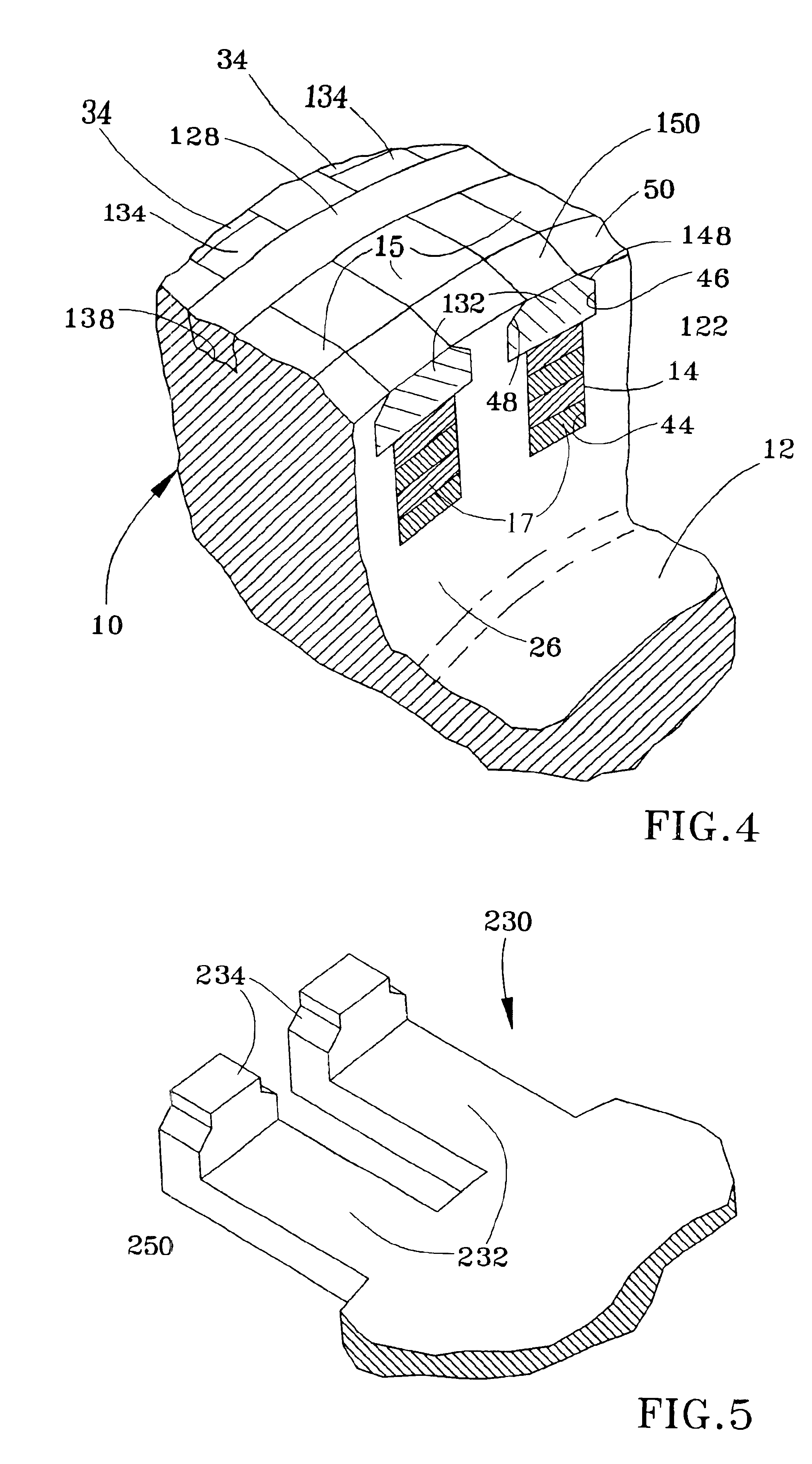
As with the rotor 10 of FIGS. 1 and 2, the rotor 10 of FIGS. 3 and 4 has a cylindrical-shaped body with an outer peripheral surface 20 and radial end surfaces 26 at oppositely-disposed ends of the cylindrical body. Furthermore, slots 14 are present in the peripheral surface 20 of the rotor 10, defining radially-extending teeth 15 (FIG. 4) at the peripheral surface 20. Field windings 17 are present in the slots 14 and axially project from the end surfaces 26 of the rotor 10. As best seen from FIG. 4, each slot 14 has a cross-sectional shape...


PUM


Abstract

A retaining system for field winding end turns of a rotor, such as for a dynamoelectric machine. The rotor has an outer peripheral surface, radial end surfaces, axially-extending slots in the peripheral surface, and field windings in the slots. The field windings axially project from the end surfaces of the rotor and are connected outside of the slots by field winding end turns. The end turns are surrounded by the retaining system, which includes a shield member surrounding the end turns and a retainer member surrounding to the shield member. The shield member has flanges received in the slots along with the field windings. Fastening features engage the flanges to inhibit axial movement of the retaining system.

Description

BACKGROUND OF INVENTION1. Field of the InventionThe present invention generally relates to rotors of dynamoelectric machines, such as generators used in the production of electrical power. More particularly, this invention relates to a retaining ring for supporting field end windings of such a rotor, wherein the retaining ring has a composite construction that provides a high-strength, low-density support structure for the field end windings.2. Description of the Related ArtLarge turbine-driven generators used in the production of electrical power comprise a rotor that serves as a source of magnetic lines of flux produced by a wound coil carried on the rotor. The rotor rotates within a stator that comprises a number of conductors in which an alternating current is induced by the rotor as it rotates within the stator, generating a rotating magnetic field in a narrow air-gap between the stator and rotor.A rotor 10 illustrative of the type used in turbine-driven generators is depicted ...

Claims


Application Information

Patent Timeline
Patent Type & Authority Patents(United States)
IPC IPC(8): H02K3/50H02K3/46H02K3/51
CPCH02K3/51
Inventor WANG, YUGHANIME, GEORGE HANNA
Owner GENERAL ELECTRIC CO
Why Eureka
Try Eureka