Automobile wheel

Inactive Publication Date: 2011-06-30
CENTRAL MOTOR WHEEL CO LTD
View PDF12 Cites 6 Cited by
  • Summary
  • Abstract
  • Description
  • Claims
  • Application Information

AI Technical Summary

Benefits of technology

[0022]According to such a configuration, the integrity between the annular front peripheral portion and the annular back peripheral portion forming the front flange portion is improved. Therefore, it is possible to prevent the folded peripheral edge portion of the front flange portion from being repeatedly locally elastically deformed as much as possible. Accordingly, the effect of mitigating a stress concentration generated on the folded peripheral edge portion of the front flange portion of the wheel disc while the vehicle is running is further improved. Furthermore, the front flange portion can exhibit high strength and rigidity. Thus, the effect of the present invention discussed above to improve the durability of the wheel against loads acting while the automobile is running is further improved.
[0023]In the automobile wheel according to an example of the present invention, as discussed above, one of the first welded portion, in which the inner peripheral end portion of the annular back peripheral portion forming the front flange portion of the wheel disc and the opening end portion of the front bead seat portion of the wheel rim are welded to each other, and the second welded portion, in which the opening end portion of the front bead seat portion of the wheel rim and the back surface portion of the wheel disc are welded to each other, is formed over the entire circumference of the wheel, and the other of the first welded portion and the second welded portion is formed over the entire circumference of the wheel or intermittently at a plurality of points along the circumference of the wheel. Meanwhile, in the automobile wheel according to another example, as discussed above, the first welded portion in which the inner peripheral end portion of the annular back peripheral portion forming the front flange portion of the wheel disc and the opening end portion of the front bead seat portion of the wheel rim are welded to each other is formed over the entire circumference of the wheel, and the second welded portion in which the inner peripheral end portion of the annular back peripheral portion of the front flange portion of the wheel disc and the back surface portion of the wheel disc are welded to each other is formed over the entire circumference of the wheel or intermittently at a plurality of points along the circumference of the wheel. According to either of the automobile wheels, it is possible to mitigate a stress concentration generated on the folded peripheral edge portion of the front flange portion and the first welded portion and the second welded portion by loads generated while the automobile is running, generally improving the durability of the wh

Problems solved by technology

The durability of the front flange portion “r” is limited by the residual stress and the stress concentration d

Method used


Image

  • Automobile wheel
  • Automobile wheel
  • Automobile wheel

Examples


first embodiment

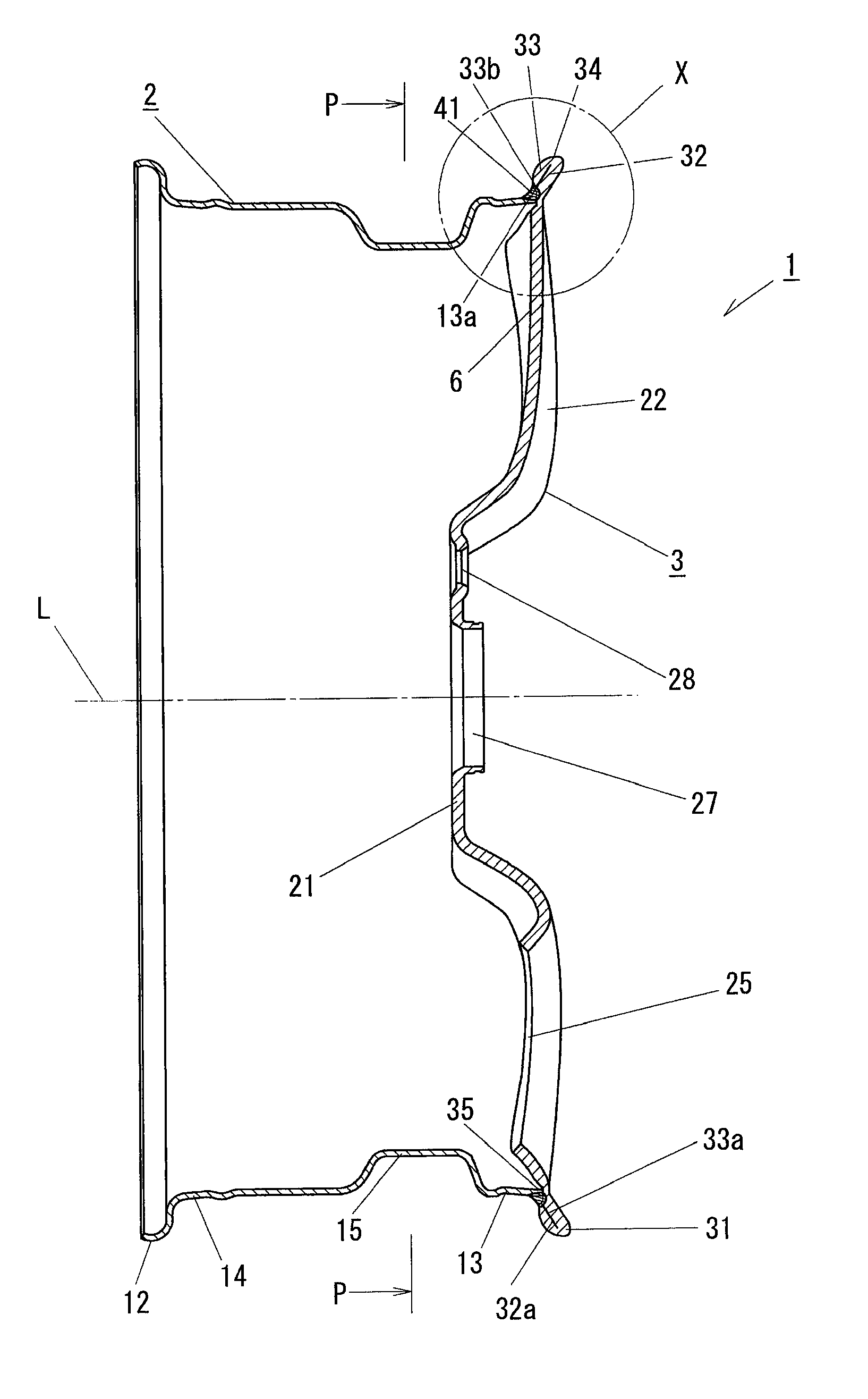
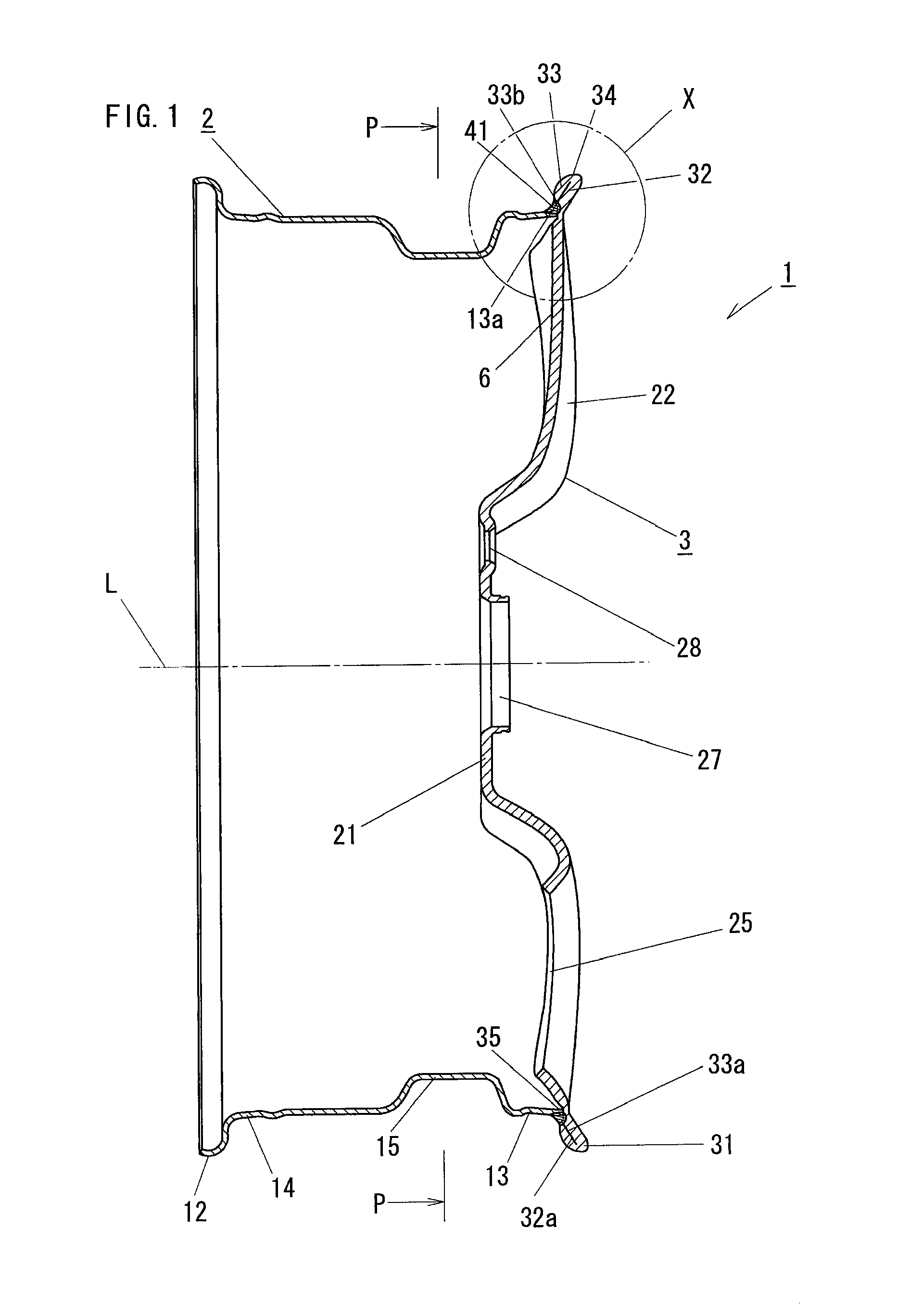
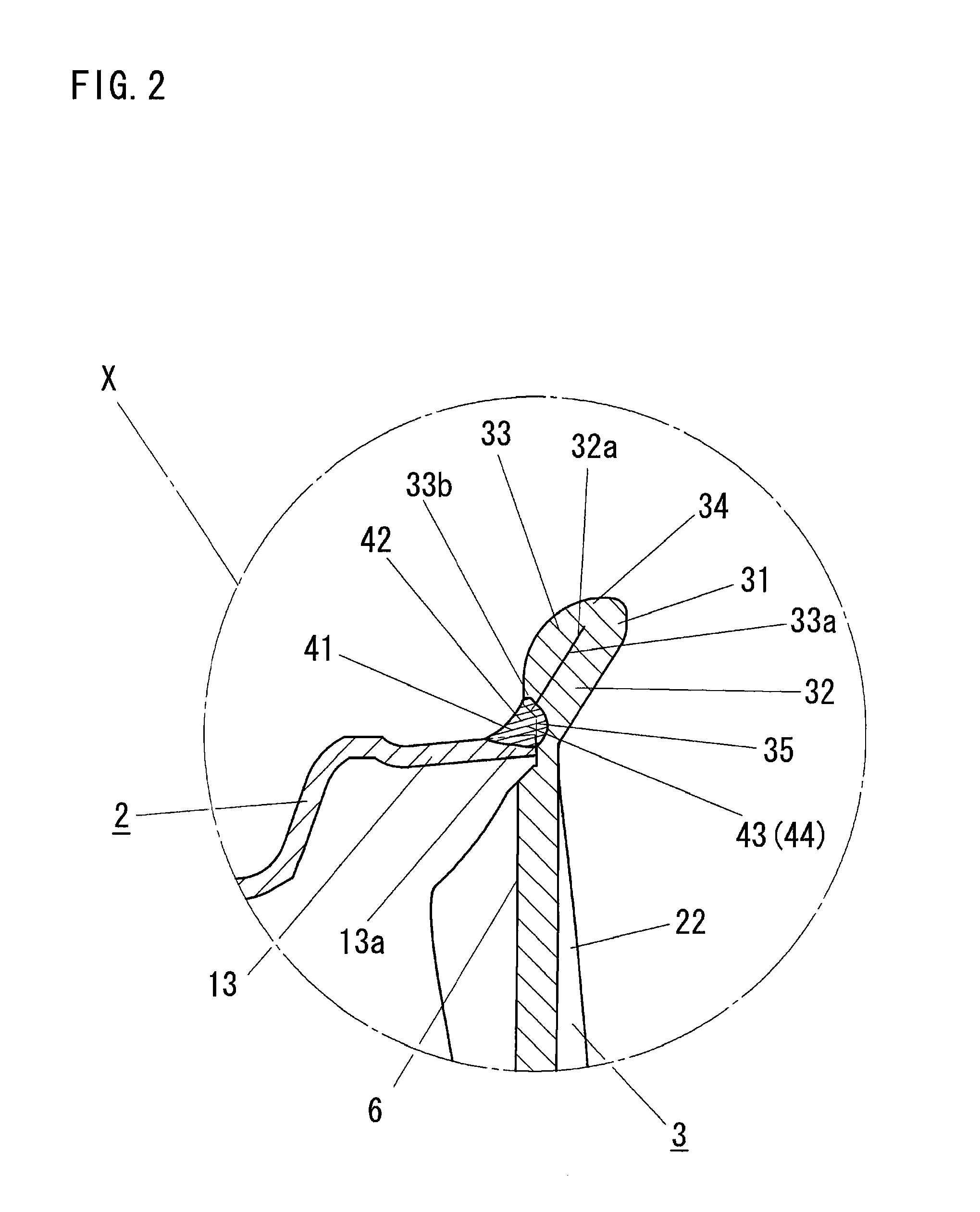
[0059]Further, the single continuous welded portion 41 is formed by three-point welding. Thus, it is possible for the continuous welded portion 41 to exhibit high strength and rigidity, and to mitigate a stress concentration on the continuous welded portion 41 due to the loads generated while the automobile is running described above. Therefore, the durability of the continuous welded portion 41 can be improved. In the configuration in particular, the single continuous welded portion 41 is formed over the entire circumference of the wheel. Thus, the durability of the continuous welded portion 41 and the front flange portion 31 can be further improved.

[0060]The thus configured automobile wheel 1 according to this example can exhibit high durability compared to the automobile wheel “m” according to the related art discussed above (see FIG. 16). In the automobile wheel “m” according to the related art, the front flange portion “r” is folded into a curved shape, and the front flange po...

third embodiment

[0075]The wheel rim 2 and the wheel disc 103 are joined to each other with the opening end portion 13a of the front bead seat portion 13 of the wheel rim 2 abutted against a back surface portion 104 of the wheel disc 103. Then, with the opening end portion 13a abutted against the back surface portion 104, an inner peripheral end portion 108b of the annular back peripheral portion 108 of the front flange portion 106 of the wheel disc 103 and the opening end portion 13a of the front bead seat portion 13 of the wheel rim 2 are arc-welded to each other over the entire circumference of the wheel from the outer side of the wheel rim 2 as shown in FIG. 12. A first welded portion 112 is thus formed. Further, the opening end portion 13a of the front bead seat portion 13 of the wheel rim 2 and the back surface portion 104 of the wheel disc 103 are arc-welded to each other at a plurality of points arranged at equal intervals along the circumference of the wheel from the inner side of the wheel...

sixth embodiment

[0078]In an automobile wheel 121 according to an example as shown in FIGS. 14A and 14B, the wheel disc 103 and the wheel rim 2 according to the example discussed above are joined to each other by the first welded portion 112 formed over the entire circumference of the wheel from the outer side of the wheel rim 2 and a second welded portion 123 formed over the entire circumference of the wheel from the inner side of the wheel rim 2. That is, this example is the same in configuration as the example discussed above except that the second welded portion 123 is formed over the entire circumference of the wheel. Therefore, constituent components of this example that are the same as those of the sixth embodiment are denoted by the same reference numerals, and are not described herein.

[0079]In the automobile wheel 121 according to this example, the first welded portion 112 and the second welded portion 123 are formed continuously with each other to form a continuous welded portion 122. The ...


PUM


Abstract

An inner peripheral end portion of an annular back peripheral portion forming a front flange portion, an opening end portion of a front bead seat portion and a back surface portion of a wheel disc are joined to each other by a first welded portion and a second welded portion. Accordingly, it is possible to prevent the front flange portion from being repeatedly elastically deformed by loads generated while the automobile is running. In addition, it is possible to mitigate a stress concentration generated on the front flange portion and the first welded portion and the second welded portion. Thus, an automobile wheel can exhibit high durability.

Description

CROSS-REFERENCE TO PRIOR APPLICATIONS[0001]Priority is claimed to Japanese Patent Application No. 2009-291653, filed on Dec. 24, 2009, which is hereby incorporated by reference in its entirety herein.FIELD OF THE INVENTION[0002]The present invention relates to an automobile wheel in which a wheel rim on which a tire is to be mounted and a wheel disc to which an axle is to be coupled are welded to each other for integration.BACKGROUND[0003]There are so-called two-piece automobile wheels in which a generally cylindrical wheel rim and a generally disc-like wheel disc are welded to each other. As such two-piece automobile wheels, there are known full-face automobile wheels in which a front flange portion is formed at an outer peripheral edge portion of the wheel disc.[0004]An example of the full-face automobile wheels is proposed in Japanese Unexamined Patent Publication No. JP-A-Hei 11-42901, for example. As shown in FIG. 16, a wheel rim “f” includes a front bead seat portion “g” provi...

Claims


Application Information

Patent Timeline
IPC IPC(8): B60B3/04B60B3/10
CPCB60B3/005B60B3/02B60B25/004B60B21/104B60B3/10
Inventor CHASHIRO, KATSUYA
Owner CENTRAL MOTOR WHEEL CO LTD
Why Eureka
Try Eureka