Fiber optic splitter package and method of manufacture

a technology of fiber optic splitter and fiber optic fiber, which is applied in the direction of optics, fibre mechanical structures, instruments, etc., can solve the problems of time-consuming, difficult, and additional equipment required, and achieve the effect of reducing the cost of assembly

Active Publication Date: 2005-03-08
CORNING OPTICAL COMM LLC
View PDF2 Cites 29 Cited by
  • Summary
  • Abstract
  • Description
  • Claims
  • Application Information

AI Technical Summary

Problems solved by technology

When those fiber optic splitters are exposed to temperature cycling, the variations in coefficients of thermal expansion may cause insertion losses in the assembly.
However, inserting the S-bends into the optical fibers is time consuming, difficult, and may require additional equipment.
Thus, such a configuration is expensive.
Additionally, the adhesives that are used to adhere the fiber optic splitters to the housing tend to degrade over time, causing further degradation of the performance of the fiber optic splitter.

Method used


Image

  • Fiber optic splitter package and method of manufacture
  • Fiber optic splitter package and method of manufacture
  • Fiber optic splitter package and method of manufacture

Examples


Embodiment Construction

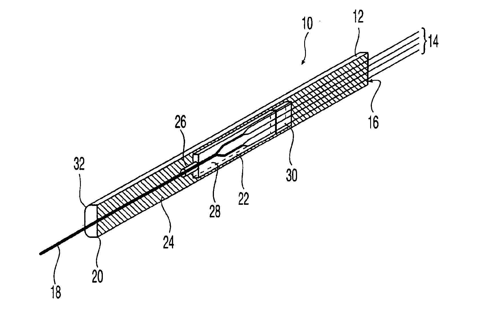
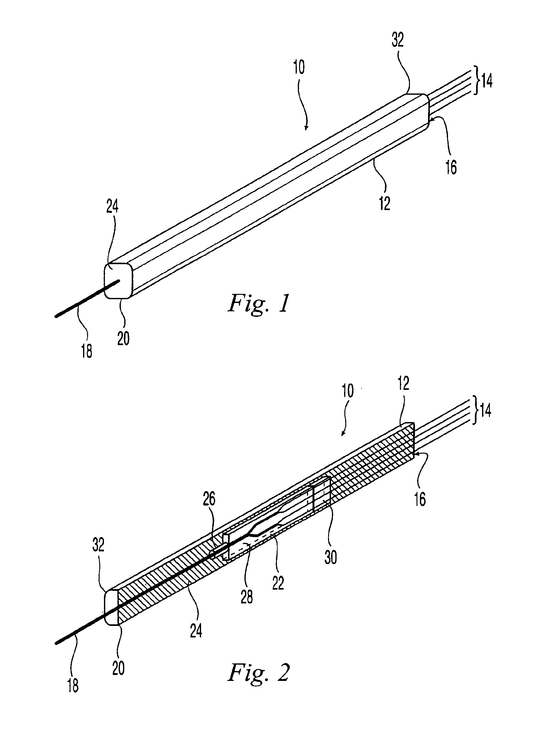
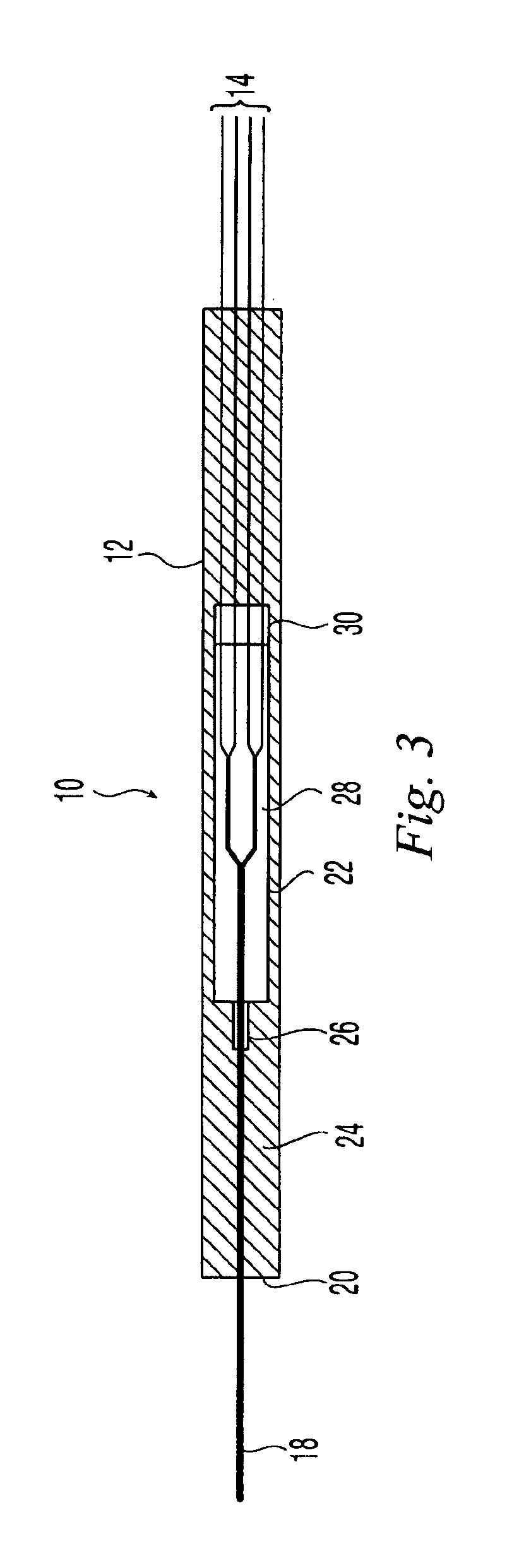
FIG. 1 illustrates one embodiment of a fiber optic splitter package 10 according to the present invention. Preferably, the fiber optic splitter package 10 has a housing 12 with a plurality of optical fibers or a fiber ribbon 14 extending from a first end 16 of the housing 12 and an optical fiber 18 extending from a second end 20 of the housing 12. As best seen in FIGS. 2 and 3, the fiber optic splitter 22 is encased in flexible retainer member 24. The fiber optic splitter 22 can be any fiber optic splitter, but the one illustrated includes a glass ferrule 26, a splitter chip 28, and a fiber array 30. The fiber array 30 allows for multiple optical fibers 14 to emerge from the fiber optic splitter package 10 either as individual fibers or as a group, bundle, or fiber optic ribbon.

The housing 12 is preferably a rigid substance, for example, stainless steel, to allow for the protection of the fiber optic splitter 22. However, the housing 12 may be made of any appropriate material that p...


PUM


Abstract

A fiber optic splitter package and method are provided for protecting a fiber optic splitter assembly while preventing adverse affects from temperature cycling. The fiber optic splitter package includes a housing, a fiber optic splitter assembly, and a flexible retainer member that holds the fiber optic splitter assembly in the housing. The flexible retainer member has a modulus of about 30 to about 80 on a Shore A hardness scale, thereby insulating the fiber optic splitter assembly from stress due to differences in the coefficients of thermal expansion of the housing and the fiber optic splitter assembly.

Description

FIELD OF THE INVENTIONThe present invention relates to a fiber optic splitter package, and more particularly, a fiber optic splitter package that provides a solution for protecting a fiber optic splitter while preventing adverse affects from stress acting on the splitter, for example, due to temperature cycling, a method of manufacturing the same, and a fixture for assembling the same.BACKGROUND OF THE INVENTIONThere are prior art methods and apparatus for protecting a fiber optic splitter, but the fiber optic splitters are adhered to an outer housing. When those fiber optic splitters are exposed to temperature cycling, the variations in coefficients of thermal expansion may cause insertion losses in the assembly. In order to avoid such insertion losses, an S-bend is typically included in the optical fibers at each end of the splitter. However, inserting the S-bends into the optical fibers is time consuming, difficult, and may require additional equipment. Thus, such a configuration...

Claims


Application Information

Patent Timeline
Patent Type & Authority Patents(United States)
IPC IPC(8): G02B6/36G02B6/30G02B6/44
CPCG02B6/3628G02B6/30G02B6/4472
Inventor SARAVANOS, COSTASMAKRIDES-SARAVANOS, ELLIHUA, YAN
Owner CORNING OPTICAL COMM LLC
Why Eureka
Try Eureka