Integrated heat spreader package for heat transfer and for bond line thickness control and process of making

a heat spreader and bond line technology, applied in the direction of cooling/ventilation/heating modification, semiconductor/solid-state device details, semiconductor devices, etc., can solve the problem of low thermal resistance, large amount of shear stress on the tim, and failure of the yield or field

Inactive Publication Date: 2005-03-15
INTEL CORP
View PDF6 Cites 66 Cited by
  • Summary
  • Abstract
  • Description
  • Claims
  • Application Information

AI Technical Summary

Problems solved by technology

One of the issues encountered when using an integrated heat spreader (IHS) is getting a balance between sufficient adhesion to the die, and a high enough heat flow to meet the cooling load of the die.
If the adhesion is insufficient, the IHS may spall off from the thermal interface material (TIM) and result in a yield issue or a field failure.
Another issue encountered is achieving an acceptable IHS standoff from the die and the board to which the board is mounted.
Due to the difference in the coefficients of thermal expansion of the IHS and the die, there is a large amount of shear stress imposed on the TIM.
A thinner TIM BLT can result in a lower thermal resistance.

Method used


Image

  • Integrated heat spreader package for heat transfer and for bond line thickness control and process of making
  • Integrated heat spreader package for heat transfer and for bond line thickness control and process of making
  • Integrated heat spreader package for heat transfer and for bond line thickness control and process of making

Examples


Embodiment Construction

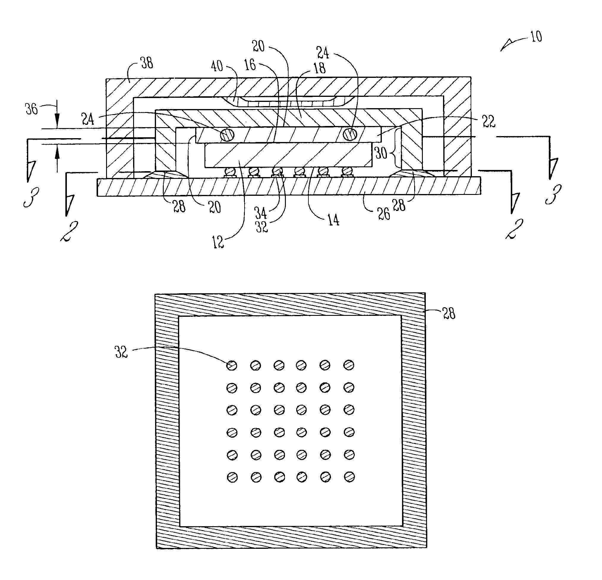
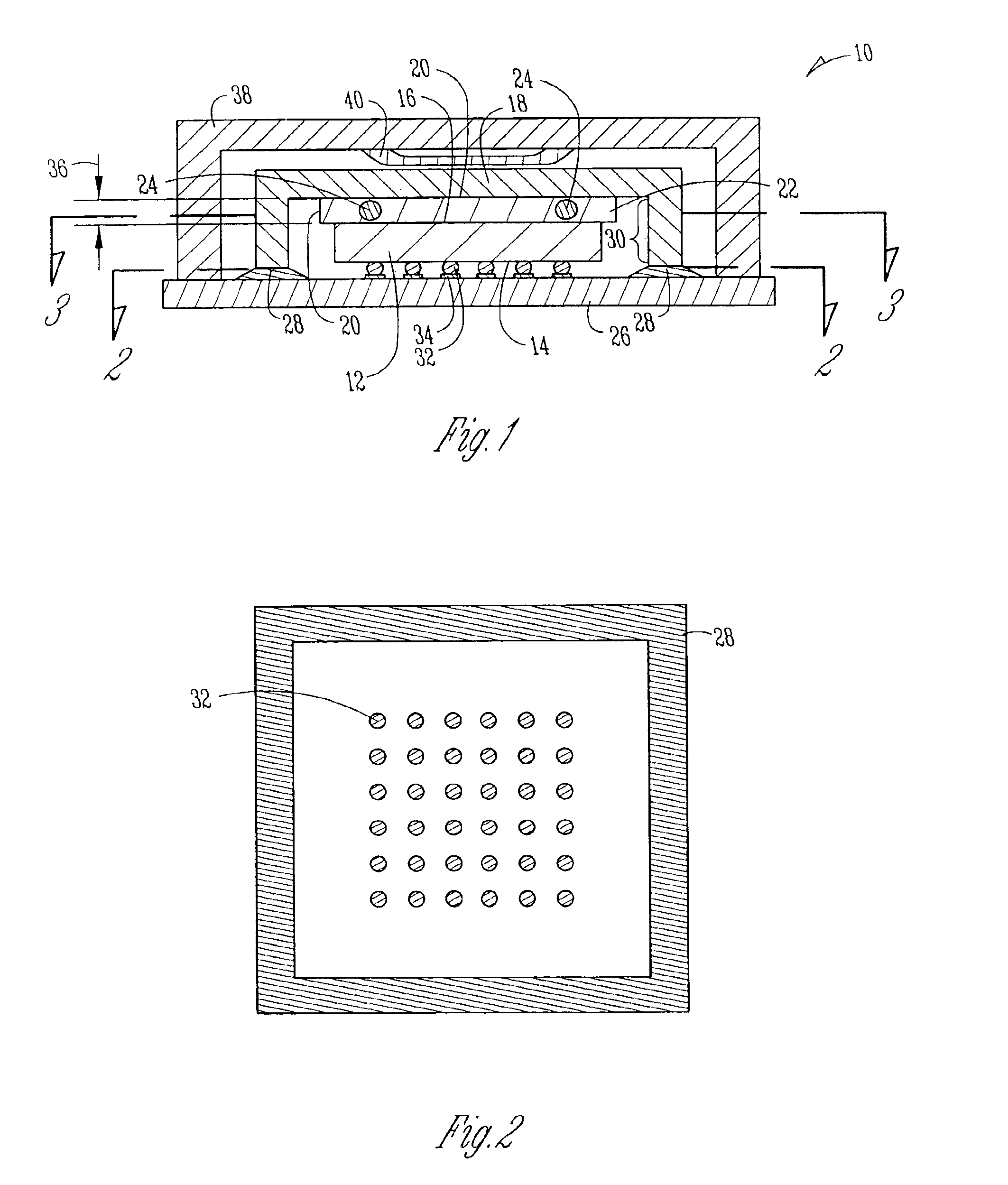
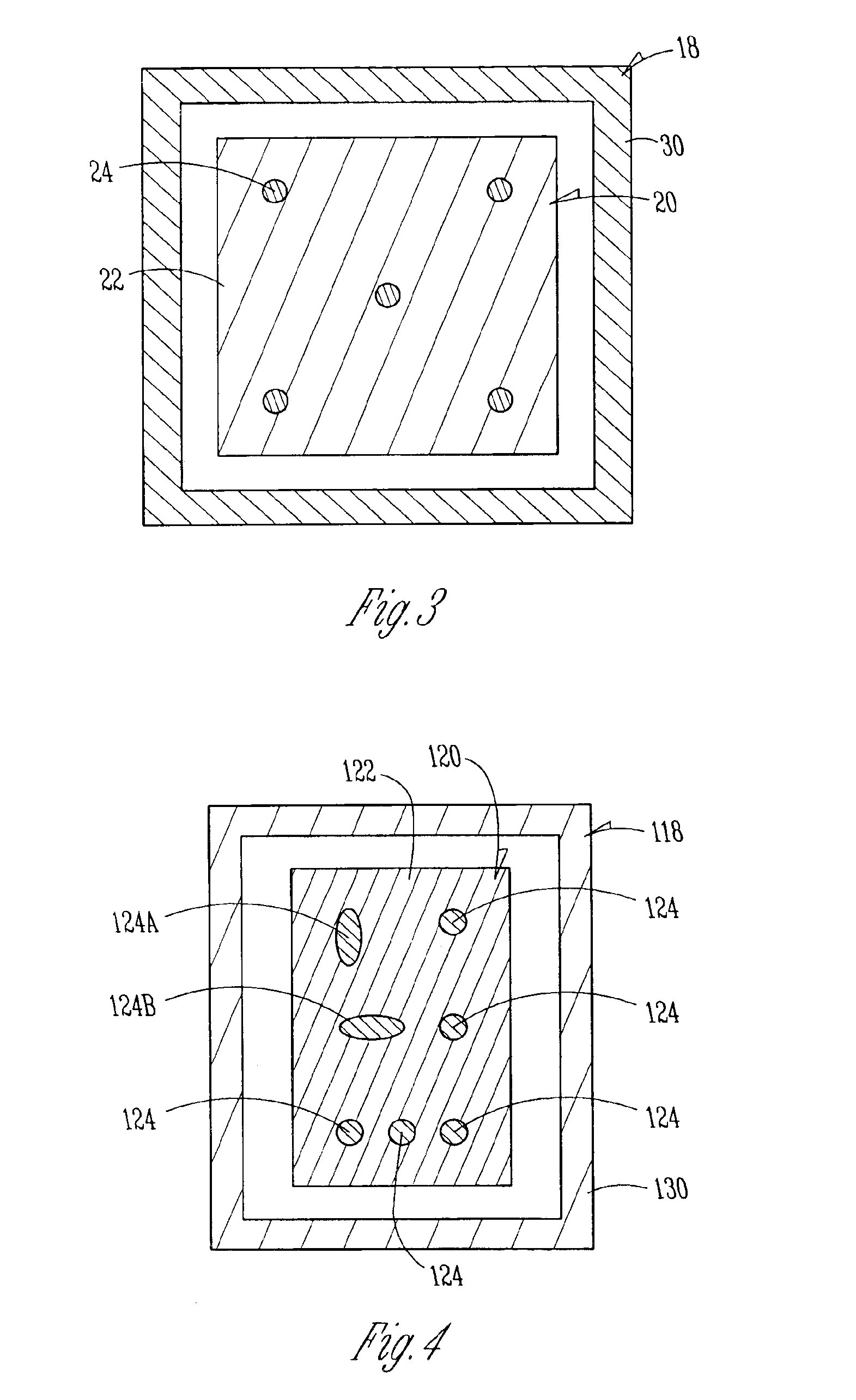
One embodiment of the present invention relates to a system that includes a thermal interface material (TIM) intermediary between a heat spreader and a die for heat transfer out of the die. One embodiment includes a method of bonding a die to a heat spreader that uses a die-referenced process as opposed to a substrate-referenced process.

The following description includes terms, such as upper, lower, first, second, etc. that are used for descriptive purposes only and are not to be construed as limiting. The embodiments of a device or article described herein can be manufactured, used, or shipped in a number of positions and orientations. The terms “die” and “processor” generally refer to the physical object that is the basic workpiece that is transformed by various process operations into the desired integrated circuit device. A board is typically a resin-impregnated fiberglass structure that acts as a mounting substrate for the die. A die is usually singulated from a wafer, and wafe...


PUM


Abstract

A system includes a thermal interface material (TIM) to transfer heat from a die to a heat spreader. The system includes a heat transfer subsystem disposed on the backside surface of the die. In one embodiment, the heat transfer subsystem comprises a first heat transfer material and a second heat transfer material discretely disposed within the first heat transfer material. A method of bonding a die to a heat spreader uses a die-referenced process as opposed to a substrate-referenced process.

Description

TECHNICAL FIELDEmbodiments of the present invention relate to an integrated heat spreader as it is bonded to a die. The bond includes a high-temperature bump or other structure that is discretely intermingled with a lower-temperature material.BACKGROUND INFORMATIONDescription of Related ArtOne of the issues encountered when using an integrated heat spreader (IHS) is getting a balance between sufficient adhesion to the die, and a high enough heat flow to meet the cooling load of the die. To deal with this issue, different bonding materials have been tried with varying results. If the adhesion is insufficient, the IHS may spall off from the thermal interface material (TIM) and result in a yield issue or a field failure. Another issue encountered is achieving an acceptable IHS standoff from the die and the board to which the board is mounted. Because of various existing processes, a substrate-referenced process is used that may cause a significant variation in bond-line thickness (BLT)...

Claims


Application Information

Patent Timeline
Patent Type & Authority Patents(United States)
IPC IPC(8): H01L23/373H01L23/433H01L23/34H05K7/20
CPCH01L23/3733H01L23/433H01L24/29H01L2924/16152H01L2224/16H01L2224/73253H01L2924/14H01L2924/00014H01L2924/00H01L2224/0401
Inventor WHITTENBURG, KRIS J.HUA, FAYDEPPISCH, CARL L.HOULE, SABINA J.BRANDENBURGER, PETERPHILLIPPE, KIM L.
Owner INTEL CORP
Why Eureka
Try Eureka