Articulated pin joint for a track chain

a technology of pin joint and track chain, which is applied in the direction of driving chains, couplings, machines/engines, etc., can solve the problems of pin and bushing joints being subject to extreme wear, high stress, and track laying work machines are subject to the most severe operating environmen

Inactive Publication Date: 2005-03-22
CATERPILLAR INC
View PDF28 Cites 17 Cited by
  • Summary
  • Abstract
  • Description
  • Claims
  • Application Information

AI Technical Summary

Problems solved by technology

In operation, track laying work machines are subject to some of the most severe operating environments.
In particular, the track chain assemblies of such work machines operate in continuous contact with abrasive, and occasionally corrosive, soil environments.
The pin and bushing joints are subject to extreme wear from the abrasive and corrosive soil environment and incur high stresses through the support of

Method used


Image

  • Articulated pin joint for a track chain
  • Articulated pin joint for a track chain
  • Articulated pin joint for a track chain

Examples


Embodiment Construction

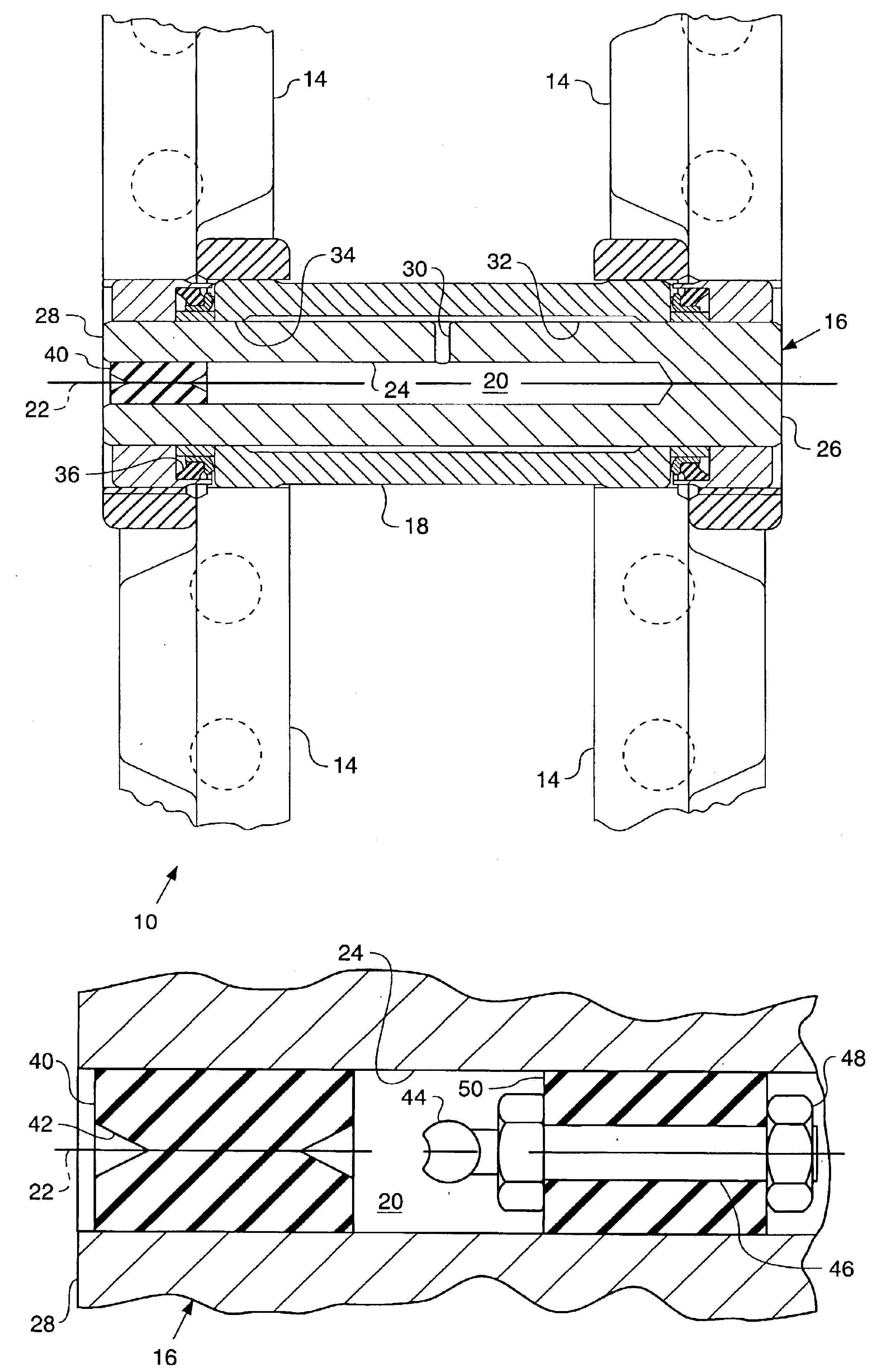
Referring to the drawings and in particular FIG. 1, a track chain 10, a portion of which is shown, includes a plurality of ground-engaging track shoes (not shown) each of which are fixedly secured to a pair of spaced, parallel, track links 14 by fasteners. Each pair of track links 14 is pivotally connected, by way of a track pin 16 and a complementing coaxially disposed bushing 18, to an adjacent pair of links 14 so that an articulated pin joint 19 is formed. The track chain 10 is entrained over a drive sprocket and at least one idler, disposed on opposite sides of a track-laying work machine (none of which are shown), in a known manner for transferring motive power to the track chain 10.

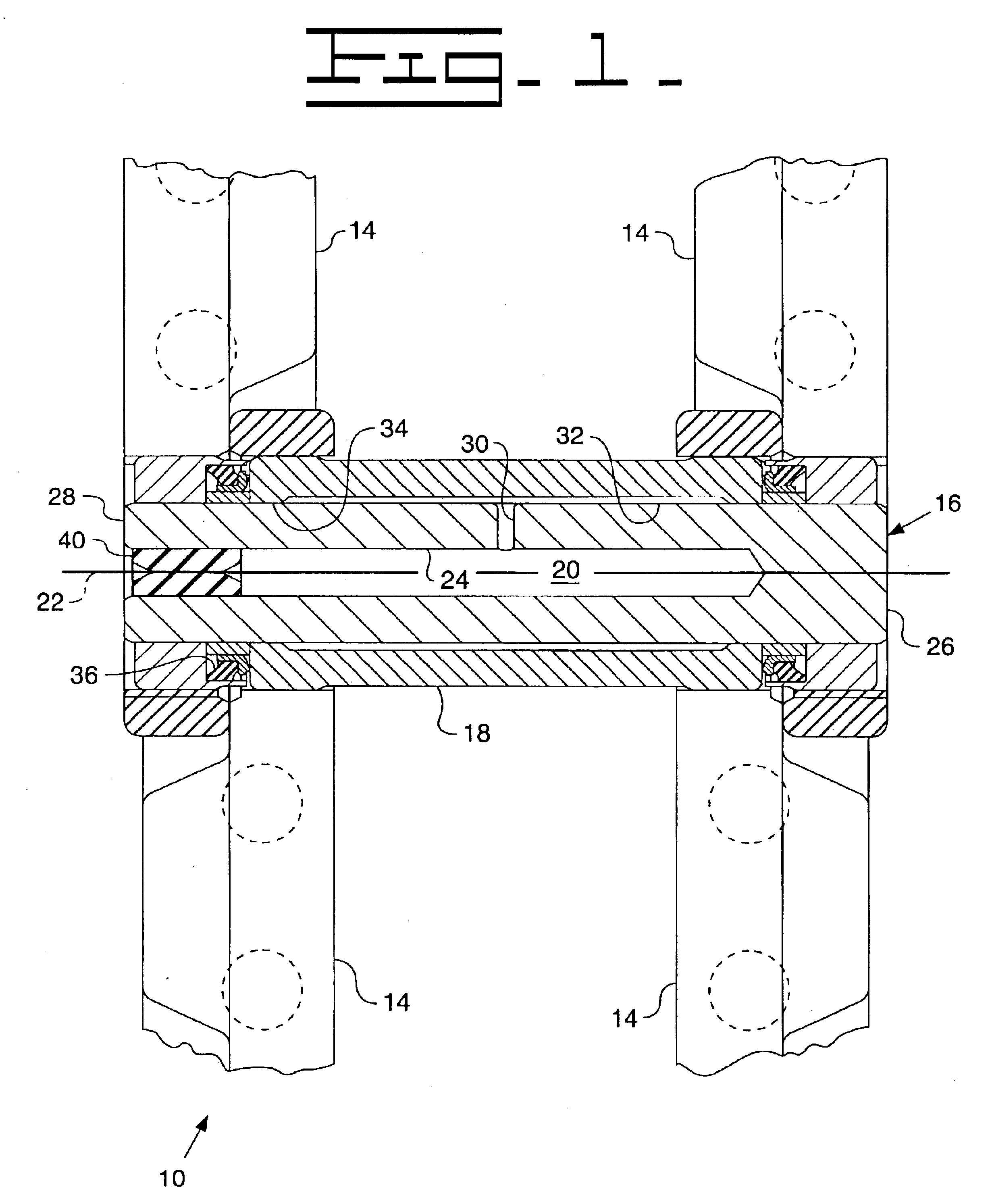
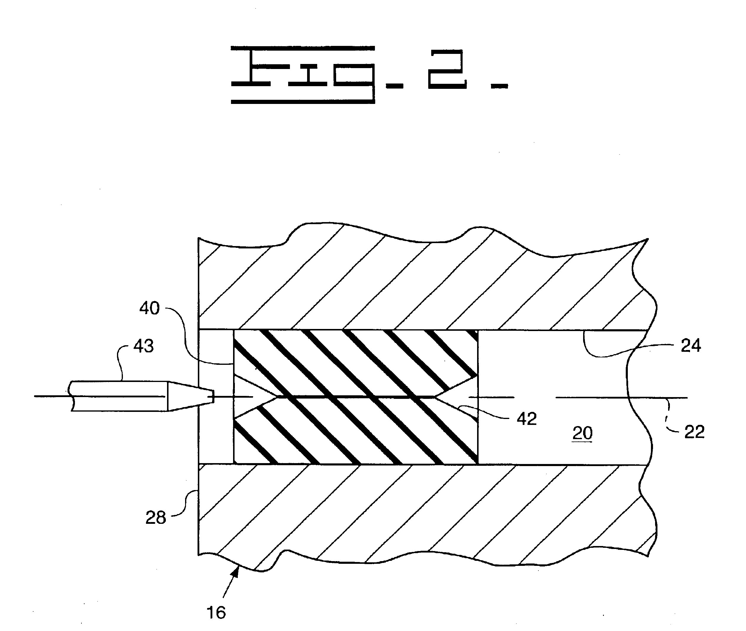
Track pin 16 includes a central cavity 20 concentrically positioned about a longitudinal axis 22. A bore 24 extends a predetermined distance through the track pin 16 to define a closed-end portion 26 at one end and an open-end portion 28 at the other end to form the central cavity 20. Central cavity...


PUM


Abstract

An improved articulated pin joint for a track chain used on track laying work machines is provided. The articulated pin joint includes a plug positioned in a central cavity of a track pin. The plug includes an axial passage in which a needle can be inserted to inject grease into the central cavity. The invention facilitates replenishing grease in the field without removing the track chain from the track laying work machine.

Description

TECHNICAL FIELDThe present invention relates to track chains for track laying work machine, and more particularly to an articulated pin joint of such a track chain.BACKGROUNDIn operation, track laying work machines are subject to some of the most severe operating environments. In particular, the track chain assemblies of such work machines operate in continuous contact with abrasive, and occasionally corrosive, soil environments. Such track assemblies include pin and bushing joints positioned between adjacent pairs of track links to hingably couple the pairs of links. Each pair of links, in turn, carry ground-engaging track shoes. The pin and bushing joints are subject to extreme wear from the abrasive and corrosive soil environment and incur high stresses through the support of the track laying work machine and the engagement with drive sprockets.Attempts have been made to increase service life of such track assemblies by improved metallurgy, factory sealing, lubrication of the joi...

Claims


Application Information

Patent Timeline
IPC IPC(8): B62D55/092B62D55/20B62D55/21B62D55/08F16G13/00F16G13/06
CPCB62D55/092B62D55/21F16G13/06Y10T403/32893Y10T403/255Y10T403/32934Y10T403/32861
Inventor ANDERTON, PETER W.ANGOT, DANIEL D.ARIANOUTSOS, STEVE L.BARNES, J. CHRISTOPHERKUPPER, DAVID G.
Owner CATERPILLAR INC
Why Eureka
Try Eureka