Automated stator insulation flaw inspection tool and method of operation

Inactive Publication Date: 2005-04-05
SIEMENS ENERGY INC
View PDF17 Cites 17 Cited by
  • Summary
  • Abstract
  • Description
  • Claims
  • Application Information

AI Technical Summary

Benefits of technology

These and other objects are achieved by an electrical generator inspection system for detecting insulation breakdown axially between two or more adjacent laminates of a generator stator core, that employs a track generally shaped to approximately conform to at least a portion of the axial profile of the generator. The track is supported proximate the axial region of the generator to be inspected. A carriage rides along and is supported by the track between the track and the generator stator core. An electromagnetic detector for identifying eddy currents flowing between laminates is support

Problems solved by technology

The result of generating the unwanted currents would be serious overheating in the core.
The insulation on a group of laminations may, however, become damaged near the bore surface during assembly, operation or maintenance.
The rotating flux will then induce currents around these circuits which can lead to troublesome overheating or hot spots in the damaged area.
If allowed to persist, the hot spots can damage or possibly cause failure of the electrical insulation around the conductors of the st

Method used


Image

  • Automated stator insulation flaw inspection tool and method of operation
  • Automated stator insulation flaw inspection tool and method of operation

Examples


Embodiment Construction

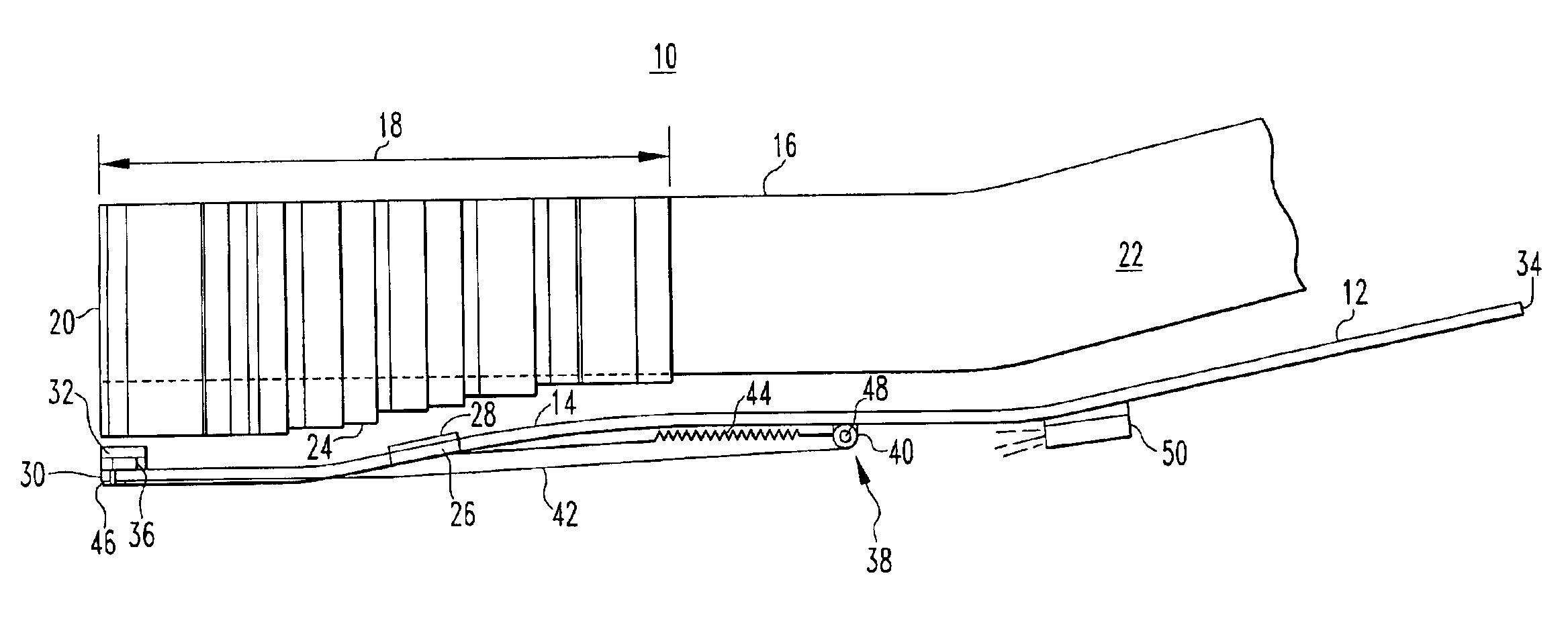
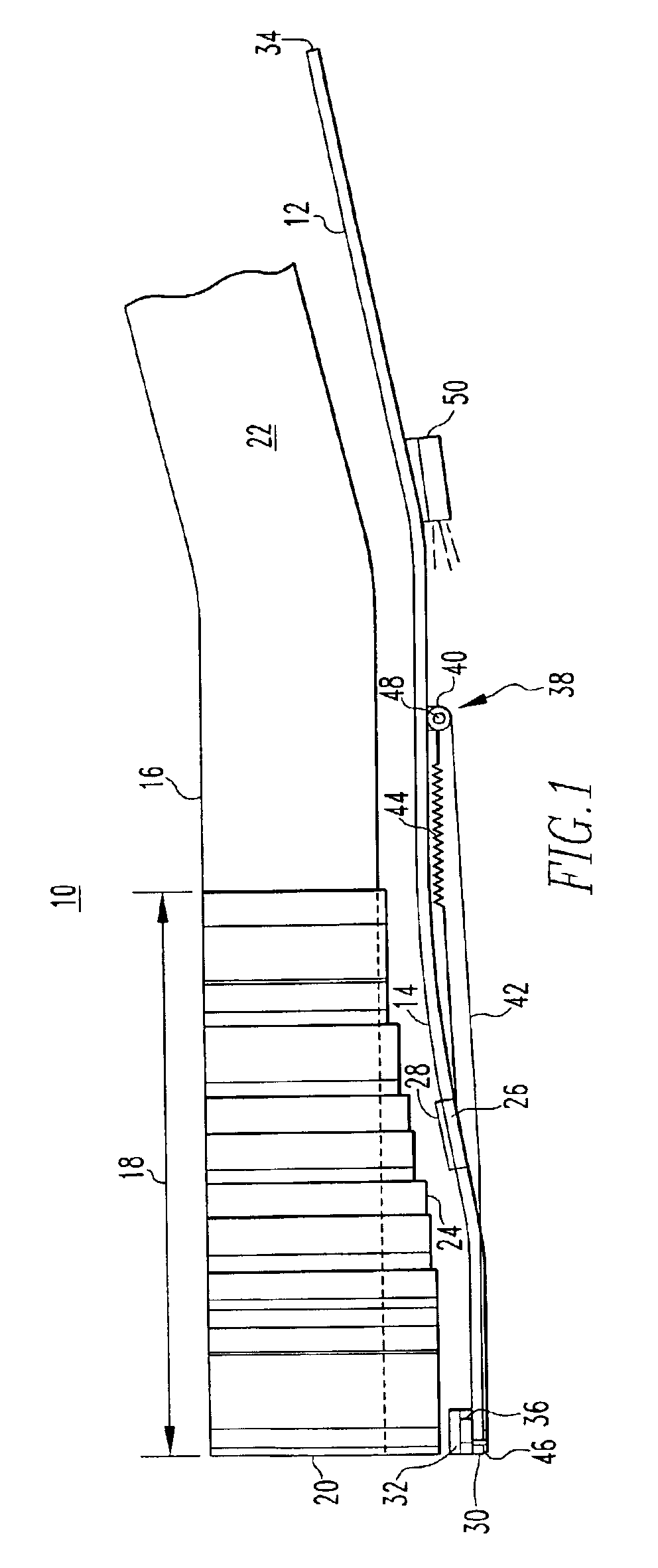
The EL CID test previously described is commonly performed on generator stator cores over the main body iron and on the step iron regions. The EL CID test is normally performed with the rotor removed, but since 1989, this test has been performed remotely with the rotor in place using a robotic carriage. The limitation of the robotic carriage is that it cannot perform the EL CID test on the step iron region of the stator core. This invention enables the step iron region to be tested with the rotor in place, and provides improved inspection techniques for performing the tests with the rotor removed. The current manual tool that is used with the rotor removed can be difficult to manipulate correctly especially over the step iron region. If the pickup coil is not handled correctly, the output readings could be distorted and mask damaged insulation. This invention overcomes those difficulties by providing an automated tool capable of accurately monitoring the step iron region of the stat...


PUM


Abstract

An automated tool for performing an EL CID inspection of the step iron region of a generator stator that can be employed with the rotor in place. The tool has a track that is axially cantilevered at one end and supported magnetically within a stator slot adjacent the region to be monitored. The track has a smoothly rounded contour that approximately conforms to the profile of the stator step region. A carriage carrying a pickup coil is slideably mounted on the track and is driven back and forth along the track over the area to be inspected by a remotely-operated drive system. A video camera is mounted on the track and provides a remote visual indication of the location of the carriage relative to the stator.

Description

BACKGROUND OF THE INVENTION1. Field of the InventionThe present invention relates generally to the inspection of electrical generators using electromagnetic detectors and, more particularly, to an automated inspection tool and method of operation that is particularly applicable to the step iron region of a generator stator and can be operated with the rotor in place.2. Related ArtThis application relates to co-pending application Ser. No. 10 / 186,048, filed Jun. 28, 2002 which describes an electromagnetic stator insulation flaw detector and method which can be employed with this invention. The stator core of a typical large generator, for example, a 500 megawatt generator, weighs 200 tons, is approximately 6 meters long, 2.6 meters in diameter and has a bore of 1.3 meters. The stator is built from a stack of approximately 200,000 individual steel sheets of laminations, each approximately 0.3 mm thick and coated, for example, with a varnish to insulate it electrically from the adjacen...

Claims


Application Information

Patent Timeline
IPC IPC(8): G01R31/34
CPCG01R31/34
Inventor FISCHER, MARK W.DAILEY, GEORGE F.BAUER, JAMES A.
Owner SIEMENS ENERGY INC
Why Eureka
Try Eureka