Systems and methods for weatherproof cabinets with variably cooled compartments

a weatherproof cabinet and compartment technology, applied in ventilation systems, electrical apparatus casings/cabinets/drawers, heating types, etc., can solve the problems of not providing different ambient environments for this equipment, cabinets also failing to provide the required ambient environments, and maintenance and repairs are difficul

Inactive Publication Date: 2005-04-12
COMMSCOPE INC
View PDF23 Cites 133 Cited by
  • Summary
  • Abstract
  • Description
  • Claims
  • Application Information

AI Technical Summary

Problems solved by technology

For example, some existing cabinets enclose electronic equipment and batteries in the same compartment and, thus, do not provide different ambient environments for this equipment.
Other existing cabinets enclose equipment, such as the electronic equipment and the batteries, in different compartments, but fail to provide sufficient cooling of this equipment—thus, such cabinets also fail to provide the required ambient environments.
Further, some existing cabinets also fail to prevent the undesirable accumulation of excessive particles and debris on enclosed equipment, such as the batteries, which may make maintenance and repairs difficult and may also contribute to decreased operating performance and life-span.

Method used


Image

  • Systems and methods for weatherproof cabinets with variably cooled compartments
  • Systems and methods for weatherproof cabinets with variably cooled compartments
  • Systems and methods for weatherproof cabinets with variably cooled compartments

Examples


embodiment 500

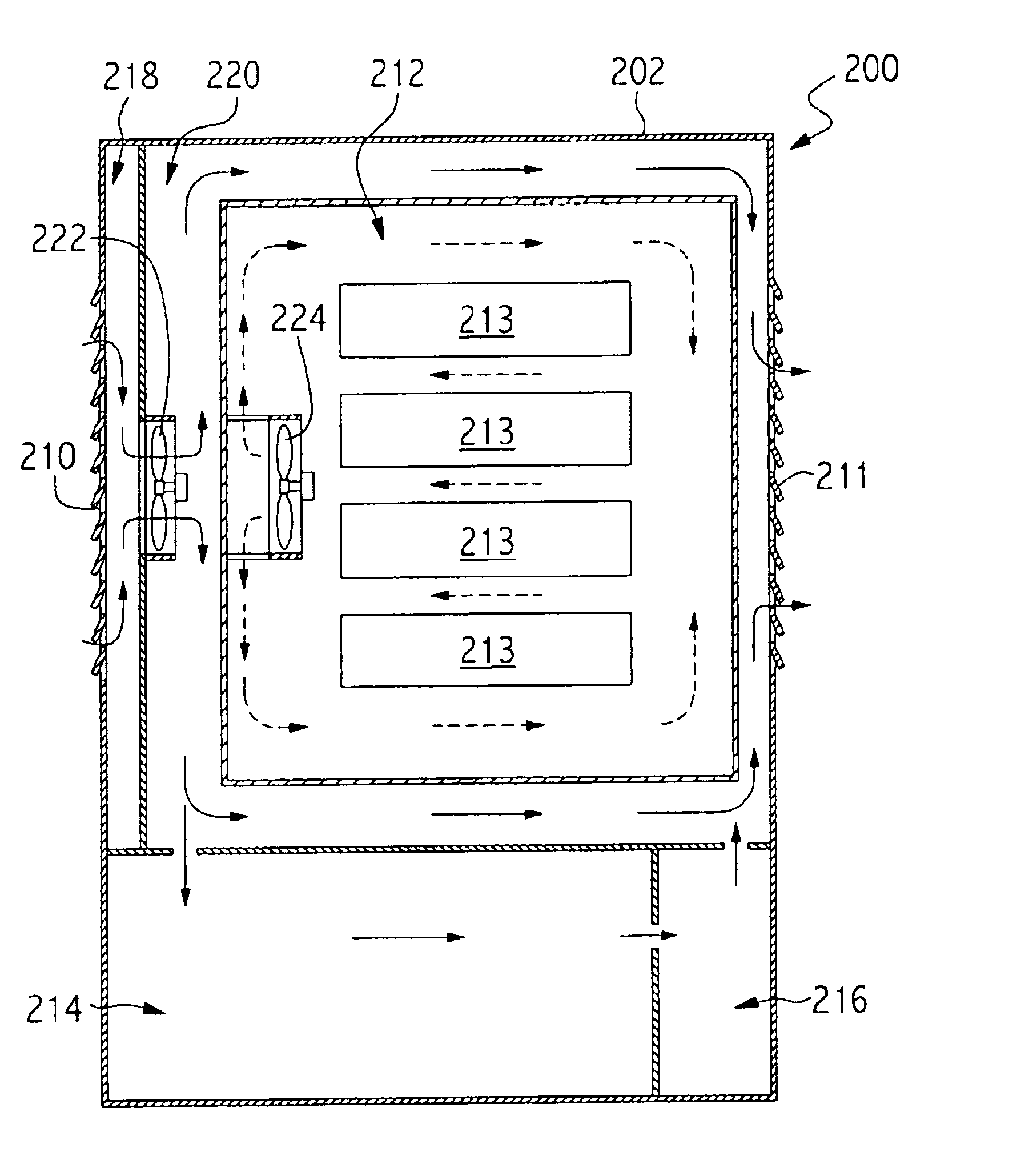
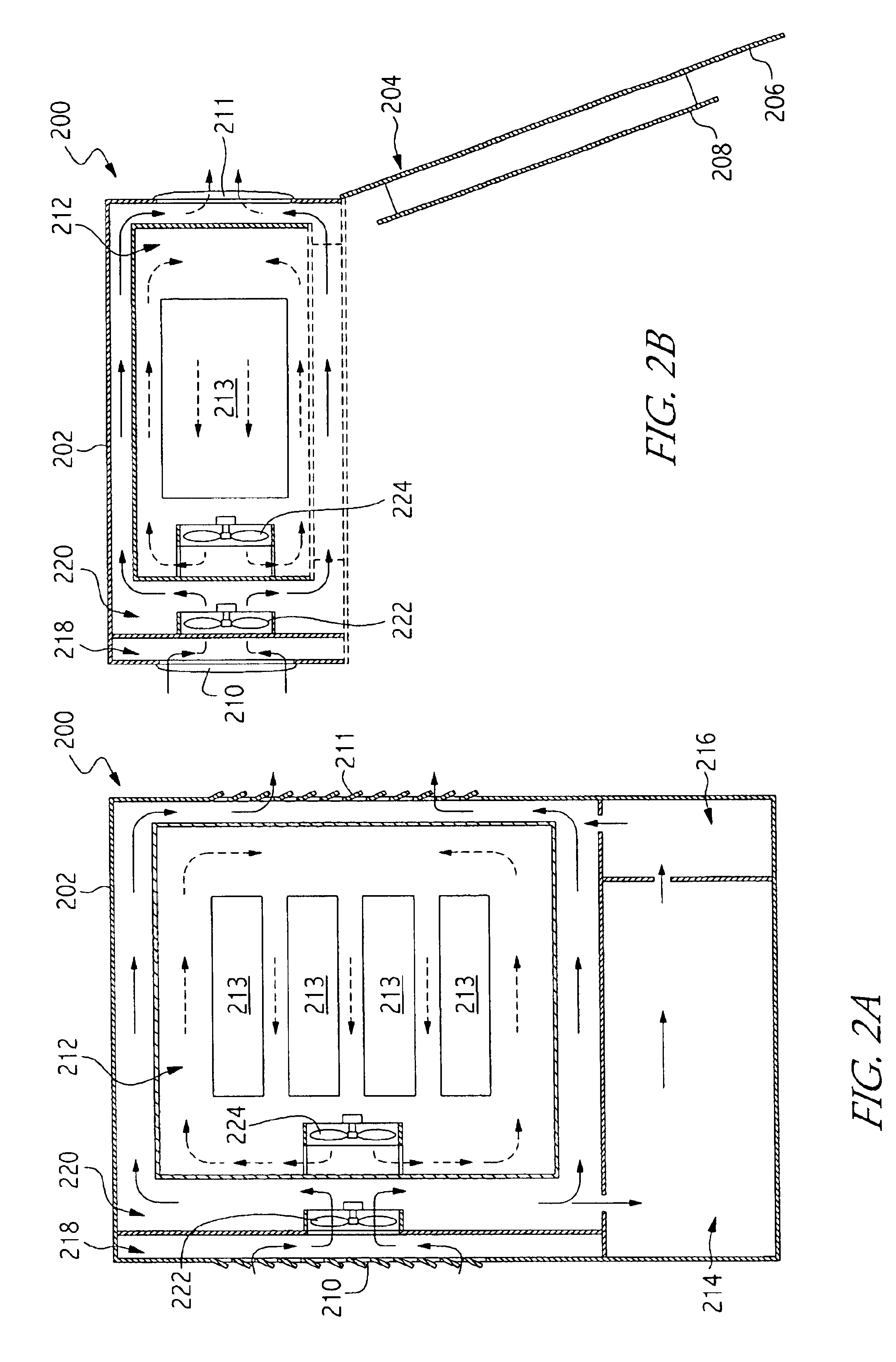
In the cabinet embodiment 500 of FIG. 5, heat is transferred from the electronic equipment 513 to the walls of the electronics compartment 513 by direct conduction, as depicted by the dashed flow lines in FIG. 5. In this regard, the electronics equipment 513 is typically attached to or in contact with some means for heat transfer, such as heat sink devices or other elements which may be know in the art, which are also attached to or in contact with one or more walls of the electronics compartment 512. Similar to other embodiments of the cabinet 500, the heat transferred to the walls of the electronics compartment 512 is typically transferred out of the cabinet 500 by the flow of external air through the cooling compartment 520 across the walls of the electronics compartment 512.

FIG. 6 is a cutaway front view of a fourth alternate embodiment of a weatherproof cabinet 600 with variably cooled compartments such as that depicted in FIG. 1 that has heat exchanging elements. This embodime...

embodiment 900

In contrast to the pushed air flow through the battery compartment 414 of the cabinet 400, in the cabinet embodiment 900 of FIG. 9, air is pulled through the battery compartment 914 by the external fans 922. In that regard, the cabinet 900 also includes one or more secondary vents 917. The secondary vents 917 have substantially similar characteristics to the right-side and left-side vents 910, 911. For example, the secondary vents 917 may be provided in various sizes, shapes, and configurations as one or more openings in the walls of the cabinet 900. Additionally, the secondary vents 917 may be shaped or otherwise configured to minimize the ingress of moisture and debris into the cabinet 900, and the secondary vents 917 may also be at least partially covered by some means for filtering (not depicted), such as those discussed above with respect to the vents 110 of FIG. 1.

The cabinet 900 also facilitates the pulled air flow through the battery compartment 914 by one or more openings i...


PUM


Abstract

Systems and methods for weatherproof cabinets with variably cooled compartments are provided. One such embodiment includes a housing having a door attached thereto, and in which a cooling compartment and a battery compartment are disposed. An electronics compartment is disposed within the cooling compartment, and an external fan is also disposed within the housing. Methods are also provided for transferring heat from inside the electronics compartment to the cooling compartment, from the cooling compartment to the outside of the housing, and from the battery compartment to the outside of the housing.

Description

FIELD OF THE INVENTIONThe present invention is generally related to telecommunications enclosures and, more particularly, is related to systems and methods for weatherproof cabinets with variably cooled compartments.BACKGROUND OF THE INVENTIONThe growing demand for telecommunications services has caused a corresponding increased demand for weatherproof cabinets that are capable of accommodating telecommunications equipment installed outdoors or in other weather exposed environments. Such cabinets are typically used to enclose electronic equipment along with batteries that provide backup power to the electronic equipment in the event that the normal power source (e.g., from a commercial utility) is interrupted. Modern telecommunications equipment, particularly newer generation electronic equipment and batteries, often require different ambient environments to function optimally. Thus, different ambient environments may need to be provided for such equipment within the same cabinet.Ex...

Claims


Application Information

Patent Timeline
Patent Type & Authority Patents(United States)
IPC IPC(8): H02B1/00H02B1/56H05K7/20H04M19/00H04Q1/02
CPCH02B1/565H04Q1/026H04Q1/035H04Q1/11H04Q1/025H05K7/206H04M19/00H04Q2201/06
Inventor STOLLER, HARRY R.
Owner COMMSCOPE INC
Why Eureka
Try Eureka