Heat-dissipating device and its manufacturing process

a heat dissipating device and manufacturing process technology, applied in waterborne vessels, blade accessories, machines/engines, etc., can solve the problems of shortening the useful life of electronic devices, affecting the heat dissipation performance of electronic devices, and generating a lot of heat on electronic devices, so as to increase the number and size of blades and enhance the heat dissipation performance

Inactive Publication Date: 2005-04-12
DELTA ELECTRONICS INC
View PDF8 Cites 11 Cited by
  • Summary
  • Abstract
  • Description
  • Claims
  • Application Information

AI Technical Summary

Benefits of technology

An object of the present invention is to provide a heat-dissipating fan and its manufacturing process for significantly increasing the number and size of blades so as to enhance the heat-dissipating performance. The heat-dissipating device has a plurality of blades arranged around the hub of the heat-dissipating device and there is an overlapped region formed between every two adjacent blades.
Another object of the present invention is to provide a heat-dissipating device having an overlapped region formed between every two adjacent blades thereof and manufactured by a single mold, which not only can reduce the manufacturing cost but can significantly increase the number and size of blades so as to increase the heat-dissipating efficiency.

Problems solved by technology

However, the electronic device will generate a lot of heat during the operating process.
If the electronic device is continuously placed in a high-temperature state, it will easily cause a damage on the electronic device and shorten its useful life.
However, under the design limitation of mold used for manufacturing the fan, the size or number of blades of the fan can not be effectively increased to improve the heat-dissipating performance of the fan.
However, this way will let the mold have an acute notch as an edge on a knife, which may be vulnerable or easily damaged.

Method used


Image

  • Heat-dissipating device and its manufacturing process
  • Heat-dissipating device and its manufacturing process
  • Heat-dissipating device and its manufacturing process

Examples


Embodiment Construction

The present invention will now be described more detailedly with reference to the following embodiments. It is to be noted that the following descriptions of the preferred embodiments of this invention are presented herein for the purpose of illustration and description only. It is not intended to be exhaustive or to be limited to the precise form disclosed.

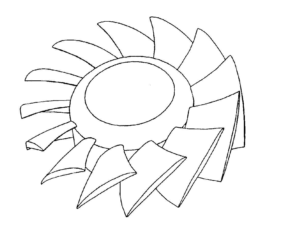
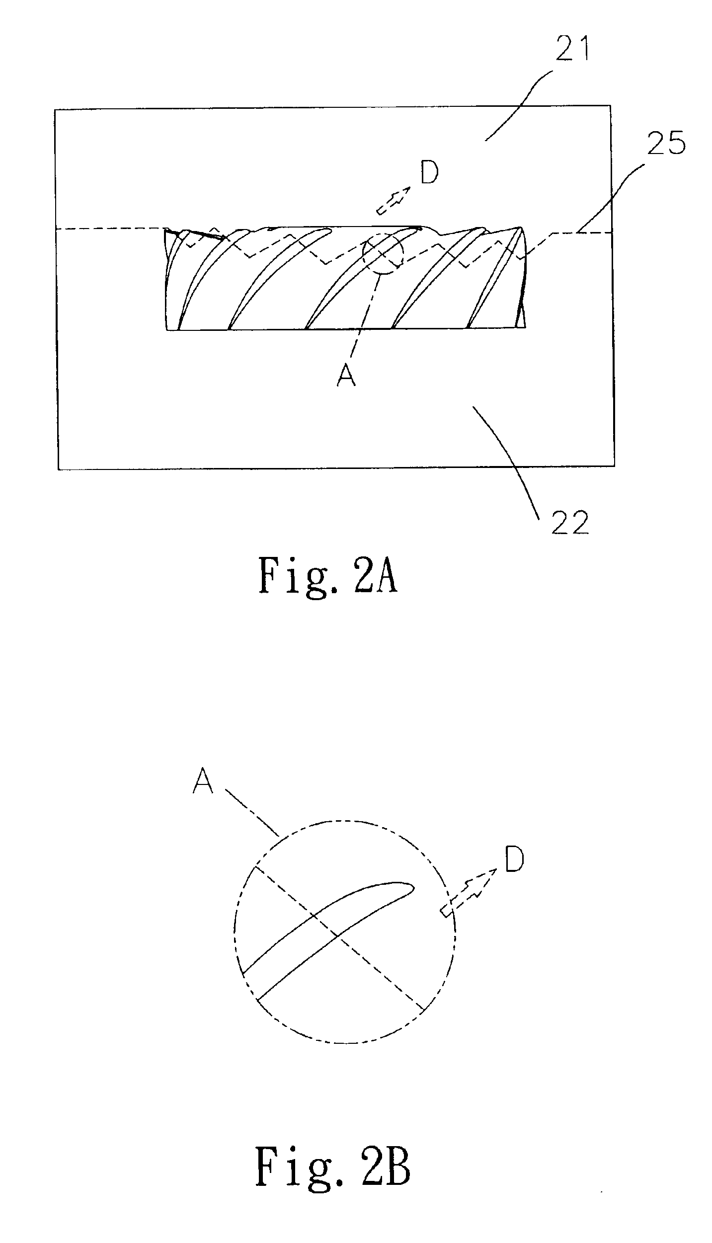
Please refer to FIGS. 2A˜2E which are schematic diagrams showing a preferred embodiment of the process for manufacturing a heat-dissipating device of the present invention. The heat-dissipating device is composed of a cup-shaped body (or called “hub”) 23 and a plurality of blades 24 arranged around the hub. There is an overlapped region formed between every two adjacent blades, that is, the region indicated by imaginary lines shown in FIG. 2E, to serve as an airflow guiding route. The manufacturing process is described in detail as follow.

First of all, a mold is provided for manufacturing the heat-dissipating device. The mold inc...


PUM

PropertyMeasurementUnit
heat-dissipating performanceaaaaaaaaaa
temperatureaaaaaaaaaa
heat-dissipating efficiencyaaaaaaaaaa

Abstract

A heat-dissipating device and its manufacturing process are provided for significantly increasing the number and size of blades so as to enhance the heat-dissipating performance. The heat-dissipating device has a plurality of blades arranged around the hub of the heat-dissipating device and there is an overlapped region formed between every two adjacent blades. A single mold is used to manufacture such a heat-dissipating device so that not only can the manufacturing cost be reduced but it can significantly increase the number and size of blades so as to increase the heat-dissipating efficiency.

Description

FIELD OF THE INVENTIONThe present invention is related to a heat-dissipating device and its manufacturing process, and especially to a heat-dissipating device having a plurality of blades and there is an overlapped region formed between every two adjacent blades for enhancing the heat-dissipating performance.BACKGROUND OF THE INVENTIONGenerally, in order to prevent the electronic device from being contaminated by particle or dust in the atmosphere, the electronic device is usually disposed in a closed housing. However, the electronic device will generate a lot of heat during the operating process. If the electronic device is continuously placed in a high-temperature state, it will easily cause a damage on the electronic device and shorten its useful life. Thus, in order to prevent the malfunction of the electronic device, a heat-dissipating fan is usually used to dissipate the heat generated by the electronic device from inside to external environment.Please refer to FIG. 1A which i...

Claims


Application Information

Patent Timeline
Patent Type & Authority Patents(United States)
IPC IPC(8): F04D29/02F04D29/00B29C33/00F04D29/32B29C45/44F04D29/38
CPCB29C33/005F04D29/38F04D29/023F04D29/325B29C45/44B29C2045/0034B29L2031/087F05D2230/53F05D2300/11F05D2300/43
Inventor LIN, CHEN-CHANGLIN, KUO-CHENGHUANG, WEN-SHI
Owner DELTA ELECTRONICS INC
Why Eureka
Try Eureka