Remote purge drying unit for compressed gas

a compressed gas and purge technology, applied in the field of air dryers, can solve the problems of limiting the mounting area of the vehicle, and affecting the drying effect of the air dryer,

Inactive Publication Date: 2005-04-12
BENDIX COMML VEHICLE SYST LLC
View PDF15 Cites 29 Cited by
  • Summary
  • Abstract
  • Description
  • Claims
  • Application Information

AI Technical Summary

Benefits of technology

In one embodiment of the present invention, a air dryer manifold is secured to an air dryer canister with a bracket located therebetween. In this embodiment, orientation pegs located adjacent to the sealing surface of the air dryer manifold and are received by a set corresponding indented regions located in a cut away region of the mounting bracket.
Another aspect of the present invention is a method of mounting an air dryer to a vehicle. In one embodiment of this invention, a mounting bracket having a recess therein is placed over a protrusion on an air dryer manifold. The mounting bracket is rotated to a desired mounting orientation and secured into such orientation by a set of orientation pegs located adjacent to the sealing surface of the air dryer manifold. An air dryer canister is then fastened to the air dryer manifold protrusion, sealing the mounting bracket therebewteen.

Problems solved by technology

Remote purge volume air dryers are typically preferred over integrated air dryers, since integrated air dryers tend to be larger and more expensive to make.
In addition, the size of an integrated air dryer limits the available mounting areas on the vehicle.
In addition to the size of the air dryer, other factors contribute to the limited available mounting area.
In addition to the limited mounting location available, current air dryers also have predefined mounting orientations.
As a result, the air dryer can only be mounted in one position.
Furthermore, air dryer canisters have a limited useful life and can only be regenerated a certain number of times before requiring replacement.

Method used


Image

  • Remote purge drying unit for compressed gas
  • Remote purge drying unit for compressed gas
  • Remote purge drying unit for compressed gas

Examples


Embodiment Construction

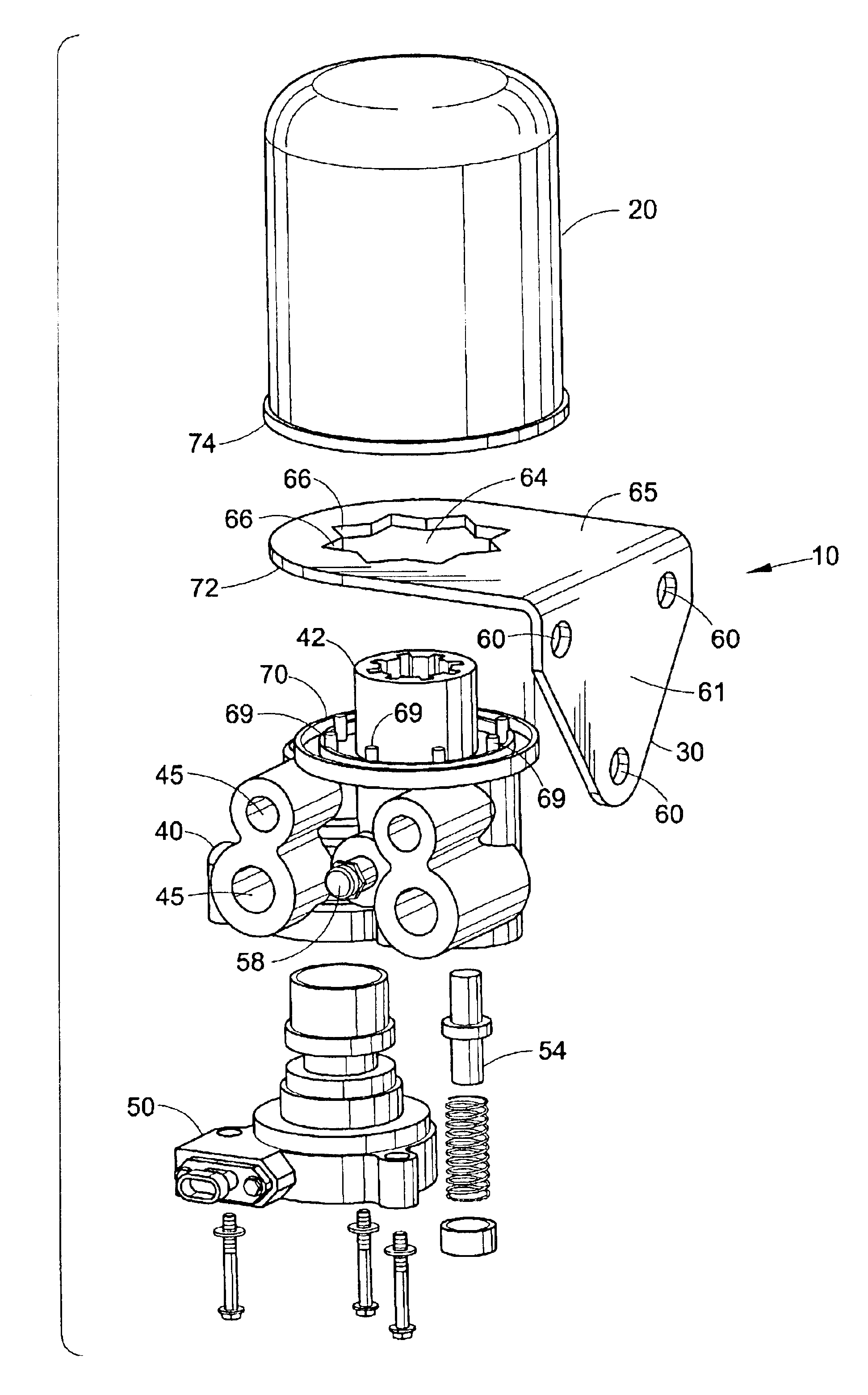
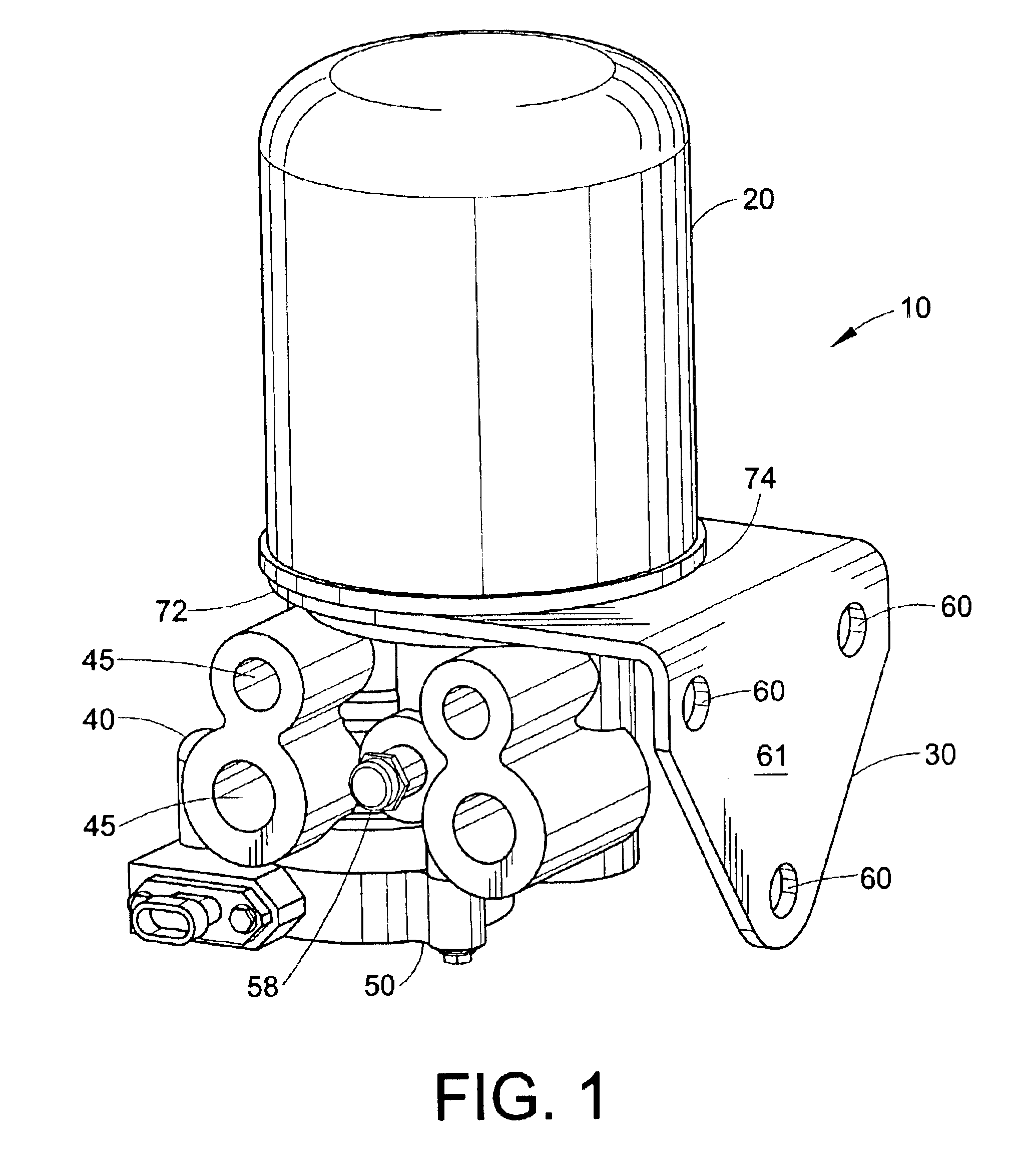
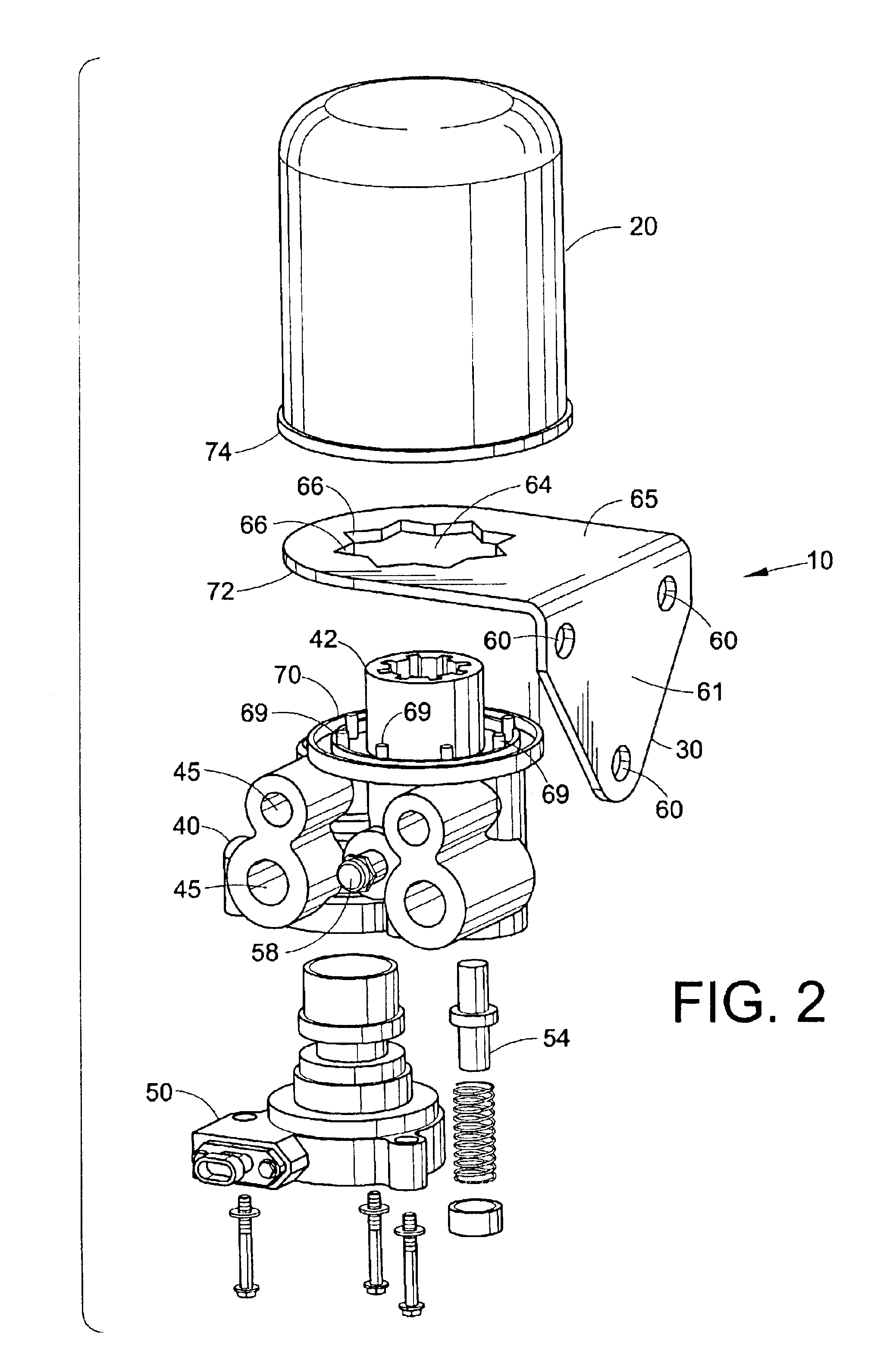
With reference to FIG. 1, an air dryer assembly, generally referenced as 10, includes an air dyer canister 20, a mounting bracket 30, and an air dryer manifold 40. As best shown in FIG. 2, the air dryer canister 20 is a conventional canister with a set of threads running through an opening on the underside of the cartridge that receives a set of mating threads 42 protruding from the center of the air dryer manifold 40. Preferably, but not necessarily, the threads 42 are between 36 mm and 50 mm. In one embodiment, the threads 42 are 41 mm, while in another embodiment, the threads are 42 mm. Optionally, an adapter can be used to make the canister 20 with 50 mm threads 42 adapt to 39 mm standard threads, for example. The air dryer manifold 40 can have any number of inlet and outlet ports 45, four such ports are shown in FIG. 2. In one embodiment, the air dryer manifold 40 includes a purge valve 50, a check valve 54, a safety release valve 58, or some combination thereof. The air dryer ...


PUM

PropertyMeasurementUnit
angleaaaaaaaaaa
angleaaaaaaaaaa
angleaaaaaaaaaa

Abstract

An air dryer assembly and mounting bracket for mounting an air dryer to a vehicle. The air dryer assembly has a manifold and a canister which seal against the surface of the mounting bracket. Orientation pegs are provided along the sealing surface of the air dryer manifold and receive corresponding indented regions in a cut out region in the mounting bracket. By providing a number of orientation pegs on the surface of the manifold, a number of mounting orientations for the air dryer assembly can be achieved.

Description

FIELD OF THE INVENTIONThis invention generally relates to an air dryer and more specifically to a method and system for mounting a remote purge air dryer used in an air braking system.BACKGROUND OF THE INVENTIONIn compressed air braking systems, such as those used on commercial vehicles, an air dryer is typically placed in line after the compressor and prior to the rest of the components, such as the compressed air reservoir or air brake units. The air dryer removes harmful contaminants, such as dirt, oil, oil vapor, water and water vapor, from the compressed air, and thus provides clean, dry air to the components of the brake system. Clean dry air increases the reliability and life of the brake system, thereby reducing maintenance costs.A typical air dryer used in air braking systems contains a desiccant canister, which includes an oil separator and a desiccant material that adsorbs water as the compressed air passes through it. The desiccant material can be regenerated by reversin...

Claims


Application Information

Patent Timeline
Patent Type & Authority Patents(United States)
IPC IPC(8): B01D53/26B01D53/04B60T17/00
CPCB01D53/0446B01D53/261B60T17/004B01D53/0415B01D2257/80B01D2259/40005Y10S55/17B01D2259/40086B01D2259/4566Y10S285/913B01D2259/40081
Inventor HOFFMAN, FREDQUINN, LEONARD A.
Owner BENDIX COMML VEHICLE SYST LLC
Why Eureka
Try Eureka