Power system for a telecommunication facility

a technology for telecommunication facilities and power systems, applied in emergency power supply arrangements, electric generator control, fuel energy technologyologies, etc., can solve the problems of increasing the current manner in which power is supplied to telecommunication facilities, and the rise of the cost of local electrical utility services in recent years

Inactive Publication Date: 2005-04-12
T MOBILE INNOVATIONS LLC
View PDF15 Cites 46 Cited by
  • Summary
  • Abstract
  • Description
  • Claims
  • Application Information

AI Technical Summary

Benefits of technology

The present invention is a schematic diagram of a device without a sensing/control mechanism. The technical effect of this invention is to provide a simplified diagram of a device without the need for additional components to control or sense its operation.

Problems solved by technology

The patent text describes a system for providing reliable electrical power to remote telecommunications facilities. The current system uses a commercial power utility and an array of batteries for backup power, which has increased costs and space requirements. The technical problem addressed by the invention is to provide a system that is more cost-efficient, requires less space, is movable, and is environmentally friendly.

Method used


Image

  • Power system for a telecommunication facility
  • Power system for a telecommunication facility
  • Power system for a telecommunication facility

Examples


Embodiment Construction

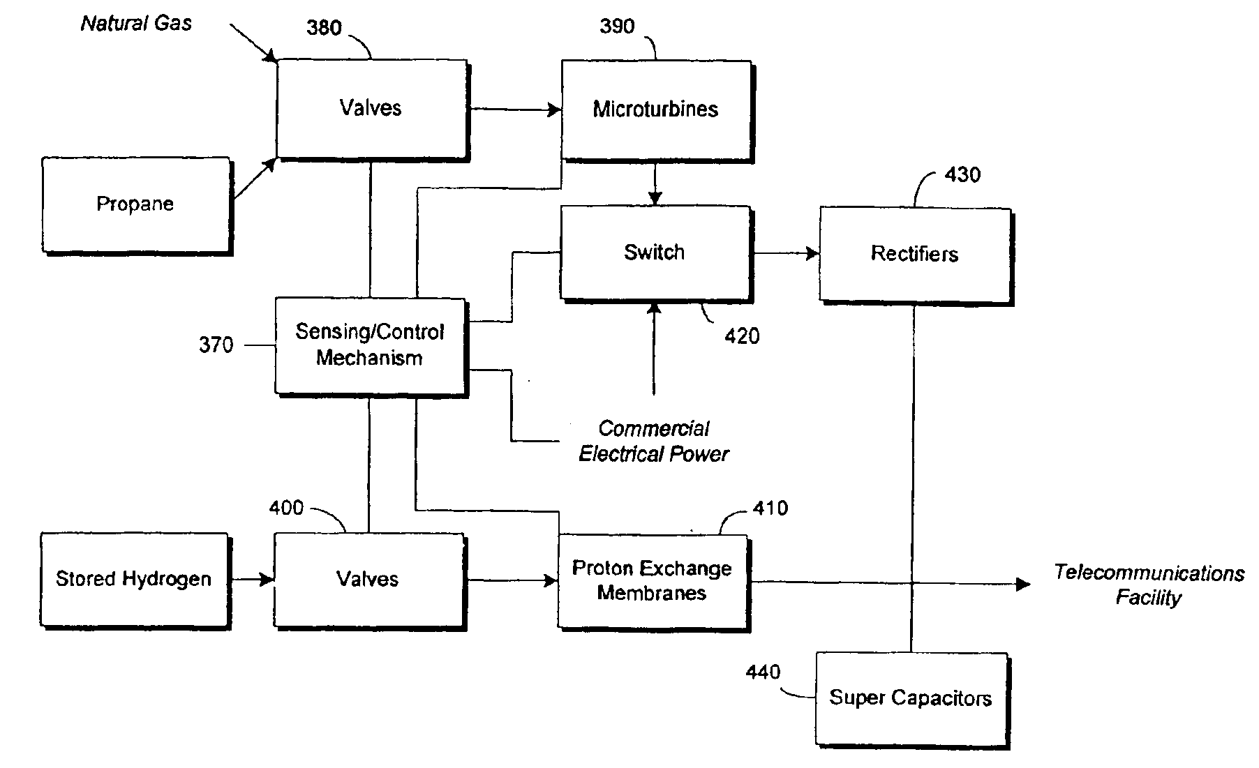
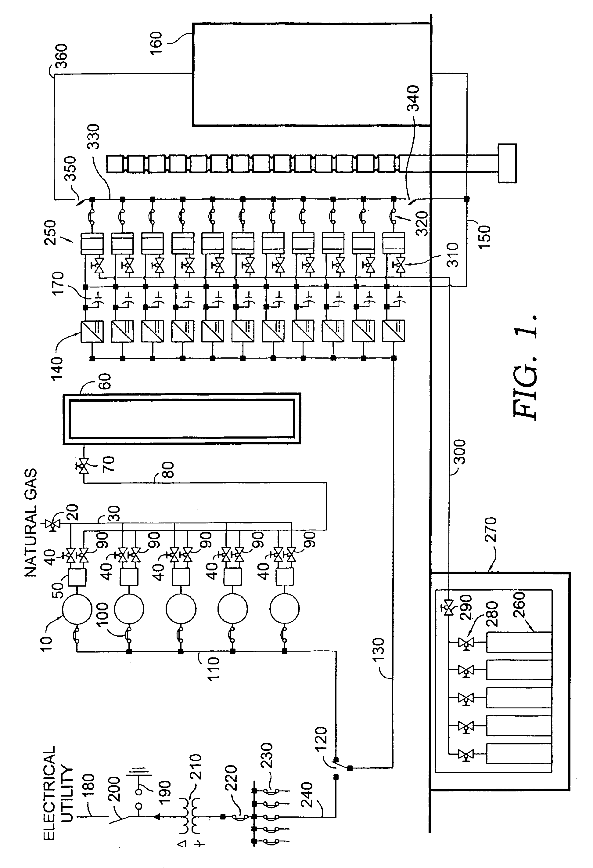
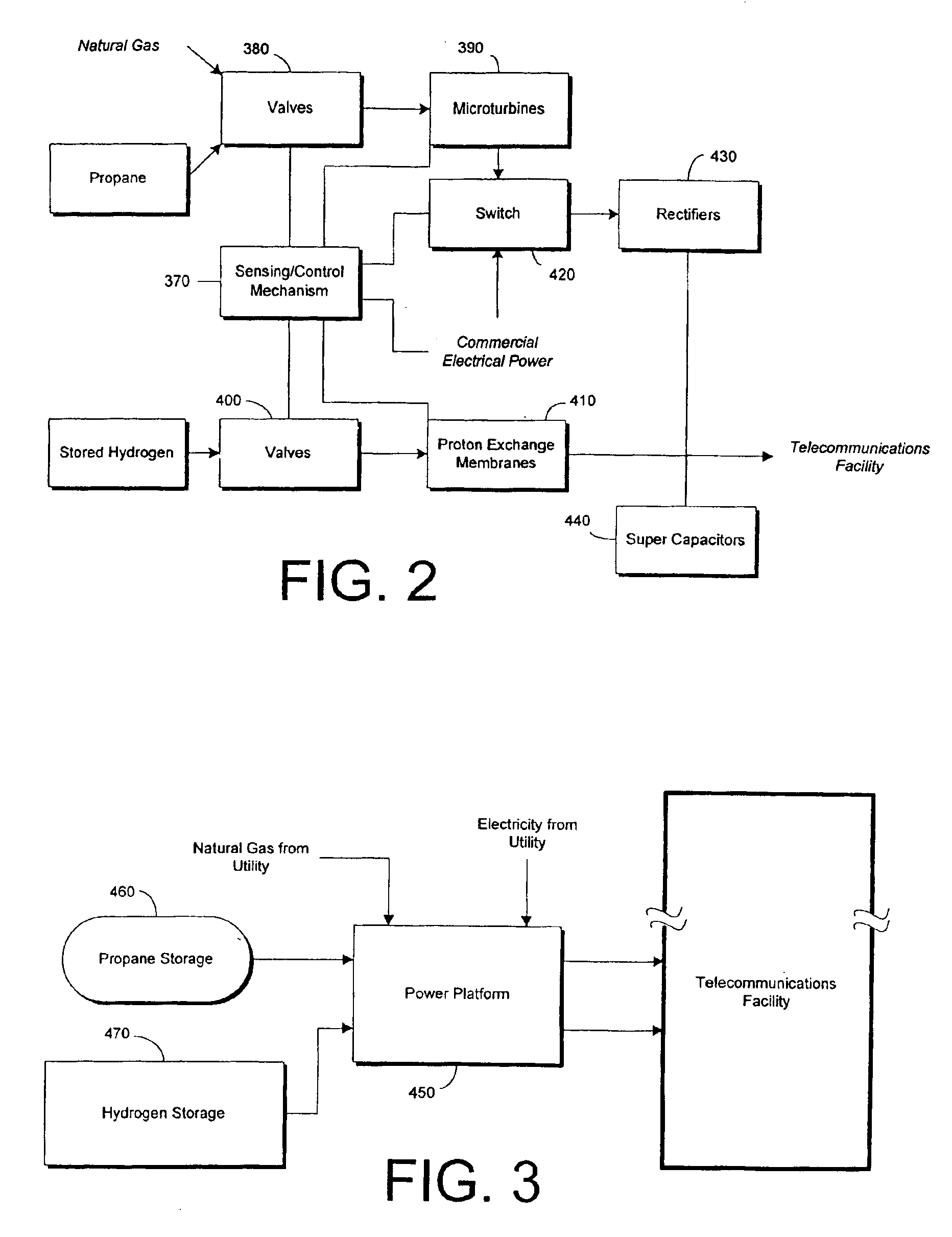
The present invention includes both a system and a method for providing reliable electrical power to a facility, and specifically to a telecommunications facility. The system provides redundant sources of electrical power including a number of microturbine generators and a number of proton exchange membranes (PEMs). The system also includes a number of capacitors to provide power during the time it takes to switch between power sources. By employing these components, the system avoids the need for an array of batteries and is more cost efficient than the current method for providing power to telecommunications facilities.

The present invention is best understood in connection with the schematic diagram of FIGS. 1-3. In FIG. 1, the power system of the present invention initially comprises a number of microturbine generators 10. A turbine includes a rotary engine actuated by the reaction or impulse or both of a current of fluid, such as air or steam, subject to pressure and an electric...


PUM


Abstract

A power system specifically designed to provide reliable electrical power to a telecommunication facility is disclosed. The system includes a number of microturbine generators adapted to provide AC power that is then rectified to DC power by an array of rectifiers. The system is configured so that the microturbine generators are fueled initially by utility-supplied natural gas. In the event the utility-supplied natural gas fails, the system provides propane from a storage tank to fuel the microturbine generators. If both microturbine generator fuel sources fail or their fuel supply becomes exhausted, power is supplied to the rectifiers by a commercial electrical utility. The system also includes a number of hydrogen-powered proton exchange membranes that are operable to supply DC power directly to the facility if both the microturbine generators and the electrical utility fail. Finally, a number of super capacitors are coupled to the bus line directly connected to the facility in order to maintain power if it becomes necessary to switch power sources.

Description


Claims


Application Information

Patent Timeline
Owner T MOBILE INNOVATIONS LLC
Why Eureka
Try Eureka