
Angle adjustment structure for electronic apparatus having display unit

a technology of electronic equipment and display unit, which is applied in the direction of wing accessories, portable frames, hinges, etc., can solve the problems of not having a structure for supporting the tablet pc, the bulk size and display unit are obviously much larger, and the majority of people cannot afford to hold the tablet pc for a long period of tim

Inactive Publication Date: 2005-04-19
INVENTEC MULTIMEDIA & TELECOM
View PDF18 Cites 30 Cited by
  • Summary
  • Abstract
  • Description
  • Claims
  • Application Information

AI Technical Summary

Benefits of technology

[0005]One objective of the present invention is to provide an angle adjustment structure of an electronic apparatus having a display unit, such that when the electronic apparatus is put on a desktop, the display unit may be adjusted to an optimal viewing angle to increase comfort.
[0006]Another objective of the present invention is to provide an angle adjustment structure of an electronic apparatus having a display unit, such that, by viewing in perpendicular to the display unit, the best resolution and color effect may be viewed.
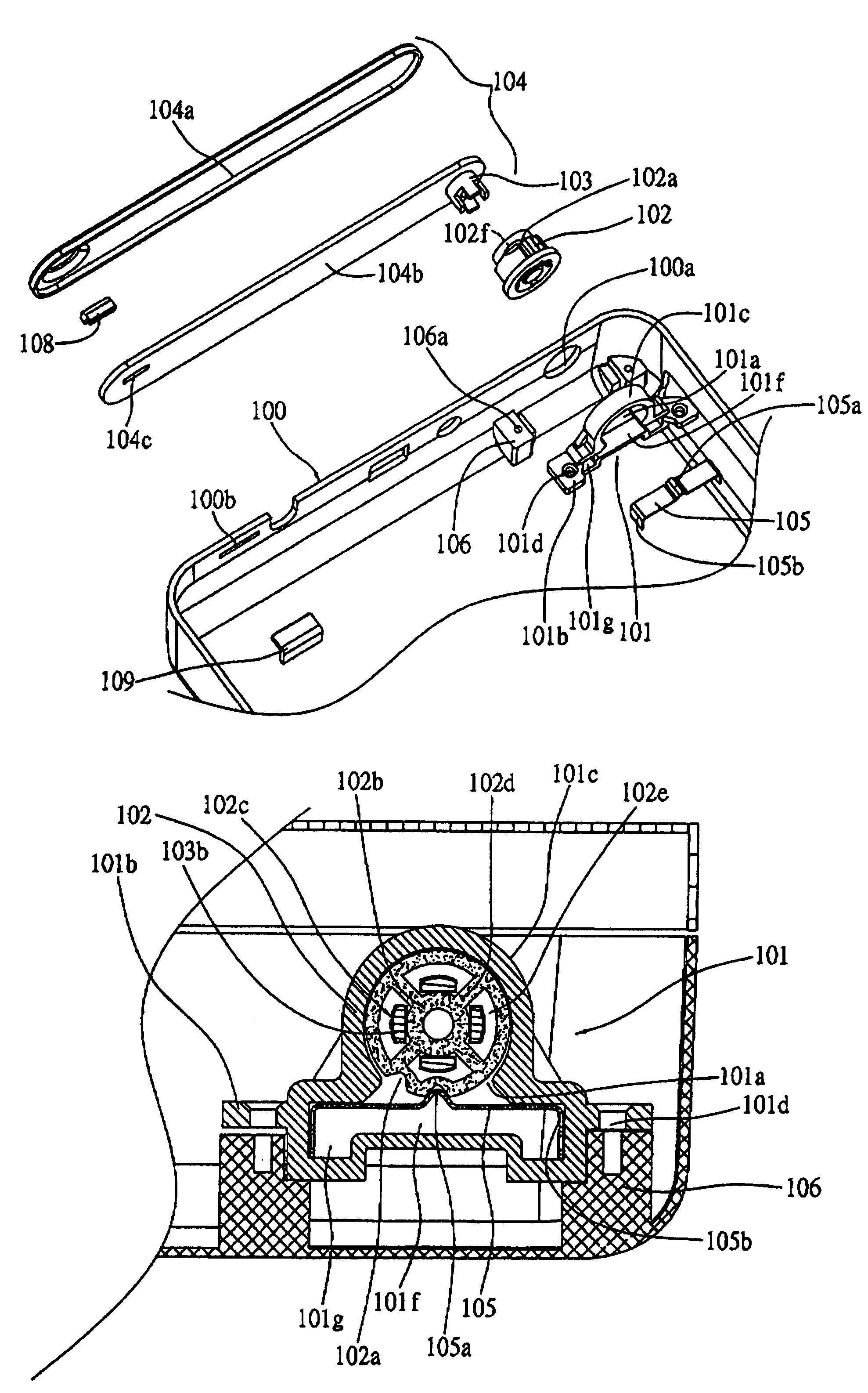
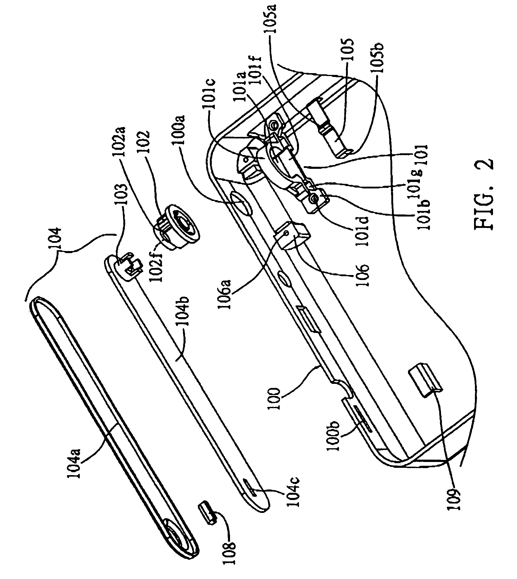
[0008]The supporting foil contained in the connection part of the shaft hole mount is comprised of some proper elastic material. At the center of the supporting foil, a curved portion of triangular cone is formed. The curved portion of the supporting foil, corresponding, to the rotation axle, according to the inclination angle of the rotation pole, a plurality of locking groove is formed. When the rotation axle connected on one end of the rotation pole rotates to the inclination angle described above, the curved portion of the supporting foil may lock in the locking groove of the rotation axle. By the locking force generated from the curved portion and the locking groove, the rotation pole may experience a rotation resistance and firmly affixed in one inclination angle. One end of the rotation pole may support the electronic apparatus on a desktop forming an inclination angle as described above. Therefore, the display unit on the electronic apparatus may maintain a perpendicular viewing angle relative to the user.

Problems solved by technology

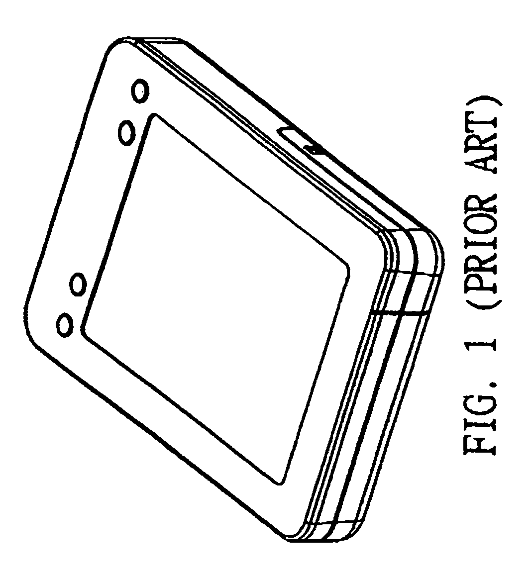
However, as shown in FIG. 1, such electronic apparatus are mostly operated by holding them in hand but not by placing them on a desktop with an optimal viewing inclination angle.
The appearance of such Tablet PC is quite similar to that of the personal data assistant (PDA), however, its bulk size and display unit is obviously much larger.
Although, it has the advantages of convenience, portability, and usability, most of people would not afford holding a Tablet PC for a long period of time.
However, since the appearance of a Tablet PC is mostly in a shape of a flat thin board, there is no structure for supporting the Tablet PC to make an inclination angle with the desktop on which the Tablet PC is placed.
If the TFT-LCD is viewed in an inclined angle, the screen would become dimmer and the color would become worse.
As of today, many electronic apparatus having a display unit may only be operated by placing it on a desktop but not in an optimal viewing angle.
This is in fact a generally existed defect in the structure and the function of the electronic apparatus having a display unit, it is thus necessary to improve such a defect.

Method used


Image

  • Angle adjustment structure for electronic apparatus having display unit
  • Angle adjustment structure for electronic apparatus having display unit
  • Angle adjustment structure for electronic apparatus having display unit

Examples


Embodiment Construction

[0015]In order to understand further the particular features and functions of the present invention, the detailed descriptions of which in accompany with the appended drawings are given in the following.

[0016]Please refer to FIG. 2 and FIG. 5, the angle adjustment structure of an electronic apparatus having a display unit of the present invention includes: a shaft hole mount 101 configured at the inner side wall of the case shell 100 of the electronic apparatus, a shaft hole 101a formed for axle connection at the center of the shaft hole mount 101, a connection part 101b configured at the bottom of the shaft hole mount 101 for locking a connection element; a rotation axle 102 configured inside the shaft hole 101a of the shaft hole mount 101 described above, a plurality of locking grooves 102a configured at the circumference outside rim of the rotation axle 102 according to the selected inclination angle; a connection pawl 103 formed at one end of a rotation pole 104 the rotation po...


PUM


Abstract

An angle adjustment structure of an electronic apparatus having a display unit is provided to position the electronic apparatus on a support plane by an inclination angle. The angle adjustment structure includes: a shaft hole mount fixed in the electronic apparatus and having a hole at a central position; a rotation axle mounted in the hole of the shaft hole mount and having a plurality of locking grooves arranged at a predetermined inclination angle; and a rotation pole having one end formed with a connection pawl, wherein the connection pawl is inserted in the rotation axle to allow the rotation pole to be rotatably mounted in the shaft hole mount. Thus, as the rotation axle is supported on the support plane by the predetermined inclination angle, the electronic apparatus positioned on the support plane is inclined to allow a viewing angle of the display unit to be adjustable.

Description

FIELD OF THE INVENTION[0001]The present invention relates generally to an angle adjustment structure of an electronic apparatus having a display unit, and more particularly, to an angle adjustment structure such that the electronic apparatus, placed on a desktop may form an adjustable inclination angle with the desktop such that the display unit may be viewed in its optimal viewing angle.BACKGROUND OF THE INVENTION[0002]In this epoch of the flourishing developments of computer information technology, all kinds of electronic apparatus has been developed and put on the market. For example, the conventional desktop computer which separates the mainframe and the display unit and occupies a lot of space, has evolved to notebook computers that integrate the mainframe and the display unit into one entity by a folding mechanism. This allows the display unit contained in the upper case to close up with the mainframe contained in the lower case. Thus, the occupation space is reduced and the p...

Claims


Application Information

Patent Timeline
Patent Type & Authority Patents(United States)
IPC IPC(8): F16C11/10F16C11/04F16M11/02F16M11/10
CPCF16C11/10F16M11/10F16M13/005Y10T16/54038F16M2200/022Y10T16/54028
Inventor KHOR, YONG-KONGWENG, SHIH-HSIUNG
Owner INVENTEC MULTIMEDIA & TELECOM
Learn More