Linear guide

a line-shaped, guide technology, applied in the direction of sliding contact bearings, linear bearings, bearings, etc., can solve the problems of excessively increasing or decreasing the clearance of one of the bearing points during readjustment, and the customer to readjust the bearing clearan

Inactive Publication Date: 2005-04-19
IGUS
View PDF7 Cites 16 Cited by
  • Summary
  • Abstract
  • Description
  • Claims
  • Application Information

AI Technical Summary

Benefits of technology

[0006]An object of the present invention is to provide an improved linear guide of the kind described above, such that it is not necessary to adjust the bearing clearance of the linear guide by means of set screws or any other adjusting elements that have to be set by the manufacturer and / or customer.
[0009]When there is excessive clearance, the steps on the surface of the adjuster slide over the corresponding steps on the sliding element until the clearance between the sliding element and the running rack of the rail is reduced to a minimum, such that the edges of the steps of both surfaces lie against one another. In this way, excessive clearance is reduced automatically, without requiring adjustment by means of a set screw or some other adjusting element.

Problems solved by technology

In many cases, however, is it necessary for the customer to readjust the bearing clearance.
There is a risk of excessively increasing or decreasing the clearance of one of the bearing points during readjustment.

Method used


Image

  • Linear guide
  • Linear guide
  • Linear guide

Examples


Embodiment Construction

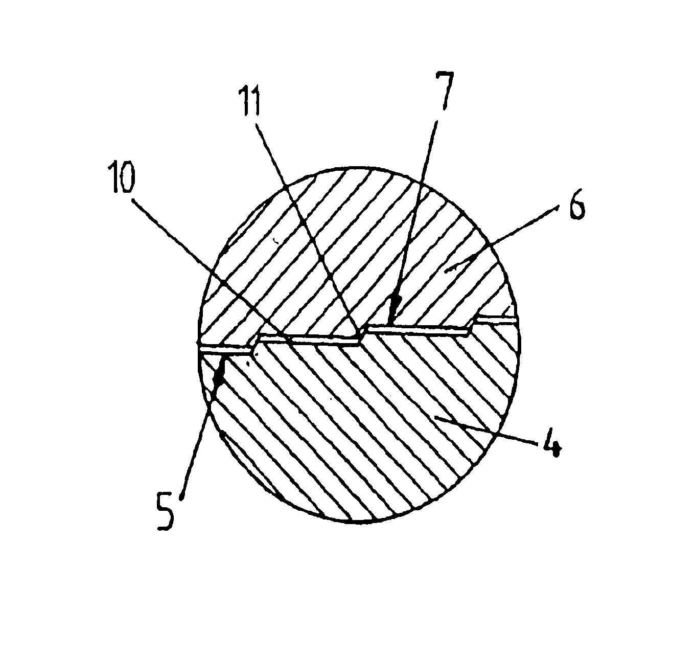
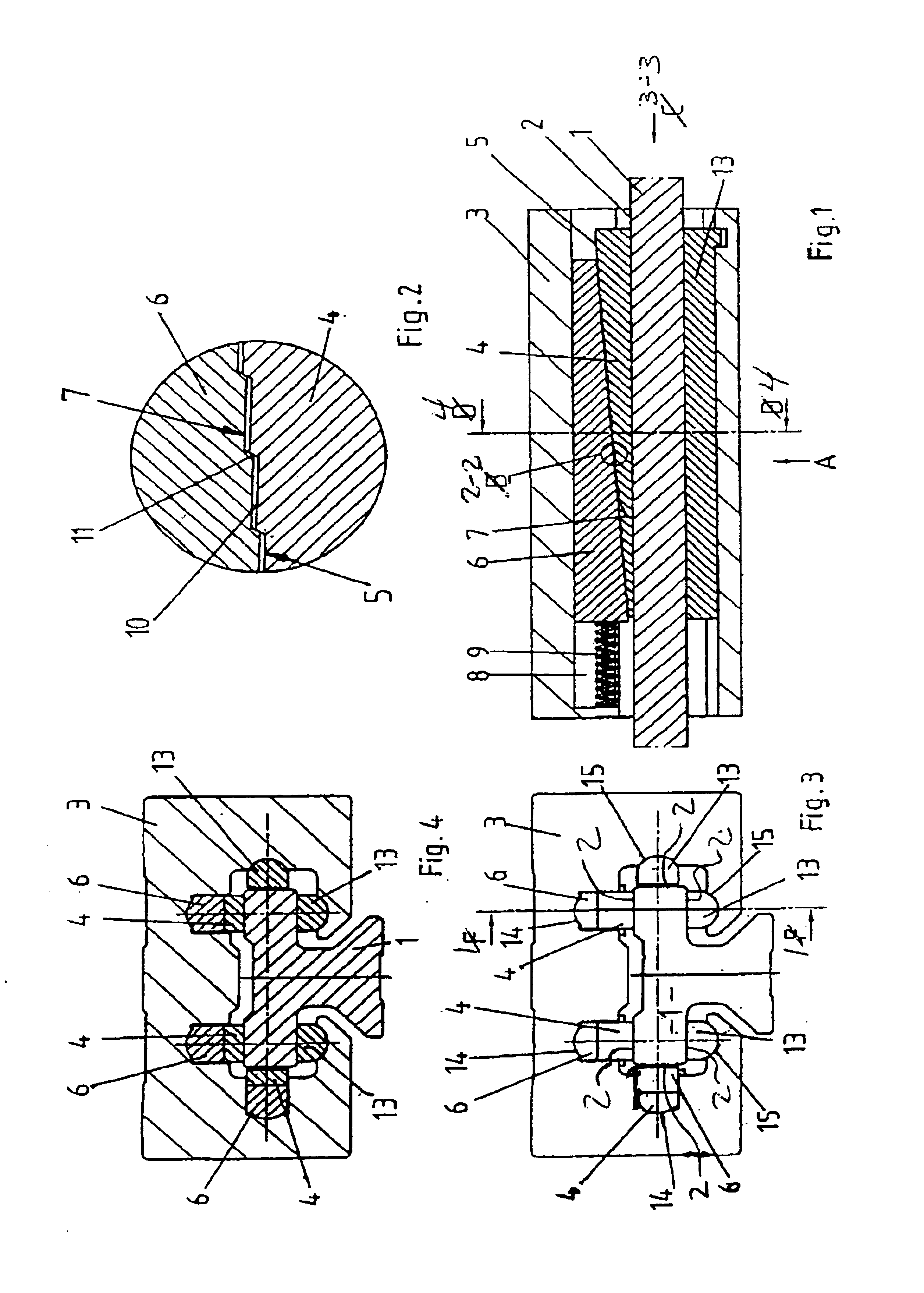
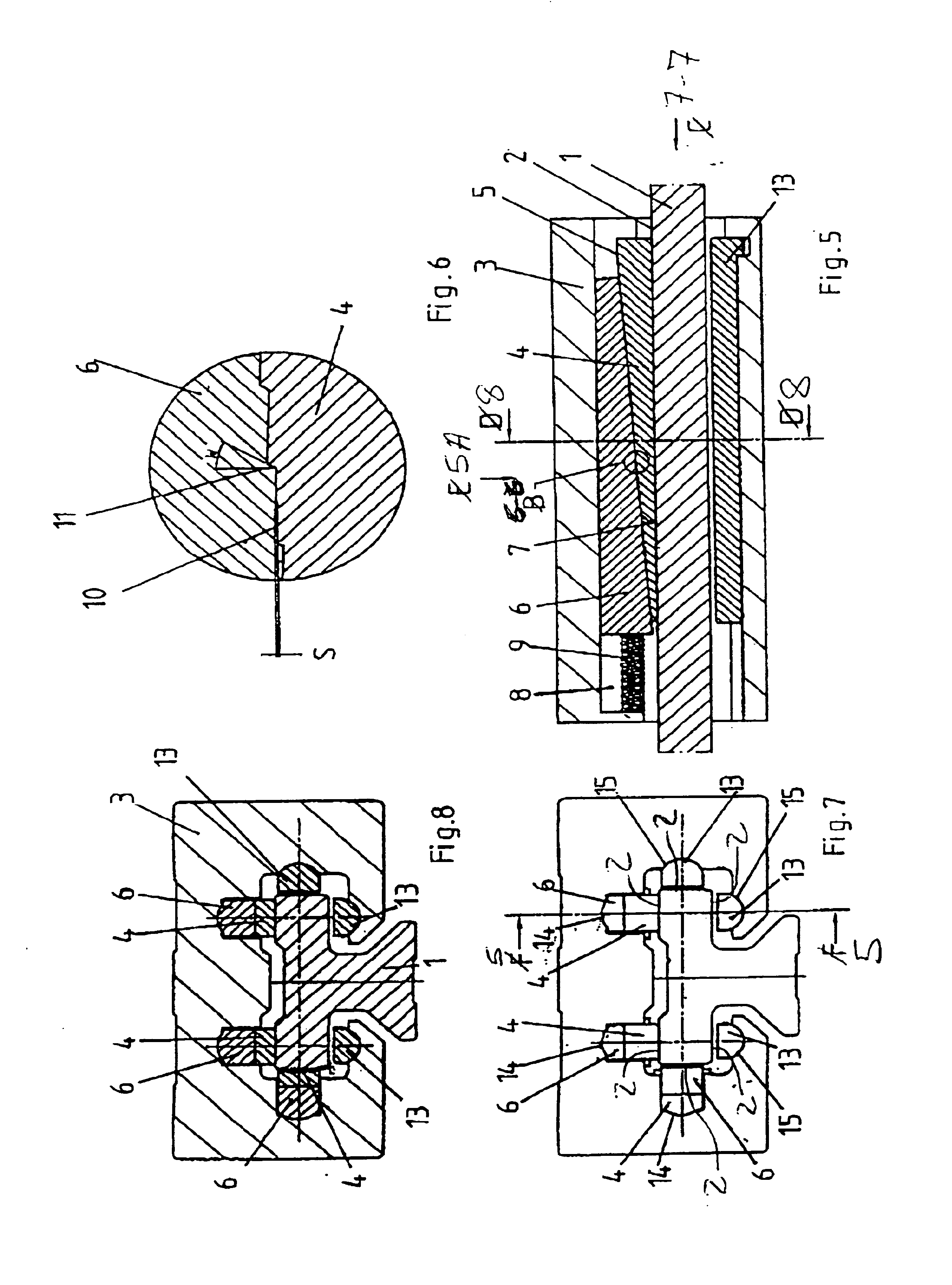
[0034]Referring now to the drawings, and to FIGS. 1, 3 and 5 in particular, a linear guide in accordance with the present invention includes a rail 1 with a plurality of running tracks 2, and a carriage 3 with wedge-shaped sliding elements 4, which are opposite running tracks 2 and have a surface 5 on the side facing away from rail 1 that is inclined relative to the travel directions of the linear guide. Provided between each sliding element 4 and carriage 3 is an adjuster 6, which can be shifted in the travel directions of the linear guide. The adjuster 6 is of wedge-shaped construction like the sliding element 4, with one surface 7 of the adjuster 6 resting in shiftable fashion against the inclined surface 5 of the sliding element 4.

[0035]As is further shown in the drawings, the carriage 3 has generally square-shaped cut-outs 8 extending in the travel directions of the linear guide for accommodating the sliding element 4 and adjuster 6. The wedge-shaped sliding element 4 and adjus...


PUM


Abstract

A linear guide comprises a linear guide comprises a rail having a plurality of running tracks, a carriage having at least one sliding element positioned opposite at least one of the running tracks, and an adjuster positioned between the at least one sliding element and the carriage. The sliding element has an inclined surface that faces away from the at least one running track and extends at an angle with respect to a travel direction of the carriage. The inclined surface has a plurality of first steps. The adjuster is shiftable in the travel direction and has an adjuster surface with a plurality of second steps that rest in shiftable fashion against the plurality of first steps. The adjuster is biased in a biasing direction against the sliding element such that the second plurality of steps can slide over the first plurality of steps as the sliding element moves in the travel direction.

Description

TITLE OF THE INVENTION[0001]Linear GuideBACKGROUND OF THE INVENTION[0002]The invention relates to a linear guide with a rail having a plurality of running tracks, and a carriage with at least one sliding element, which is opposite the running tracks and has a surface on the side facing away from the rail that is inclined relative to the travel directions of the linear guide, where an adjuster that is provided between the sliding element and the carriage can be shifted in the travel directions of the linear guide and has a surface resting in shiftable fashion against the inclined surface of the sliding element.[0003]A linear guide of this kind is known from the applicant's “DryLin® T” catalogue of 8 / 98. It comprises an essentially T-shaped rail and a carriage with a correspondingly designed channel. The rail has two first pairs of running tracks that are opposite one another and perpendicular to the normal load direction of the carriage, and one second pair of running tracks that are...

Claims


Application Information

Patent Timeline
Patent Type & Authority Patents(United States)
IPC IPC(8): F16C29/00F16C29/02F16C25/04F16C29/12
CPCF16C29/02F16C29/126F16C29/12F16C33/20
Inventor MOSHAMMER, HORST
Owner IGUS
Why Eureka
Try Eureka