

Indication systems and methods
- Summary
- Abstract
- Description
- Claims
- Application Information
AI Technical Summary
Problems solved by technology
Method used
Image

Examples
Embodiment Construction
[0017]The description below pertains to several illustrative embodiments of the invention. Although many variations of the invention may be envisioned by one skilled in the art, such variations and improvements are intended to fall within the compass of this disclosure. Thus, the scope of the invention is not to be limited in any way by the disclosure below.
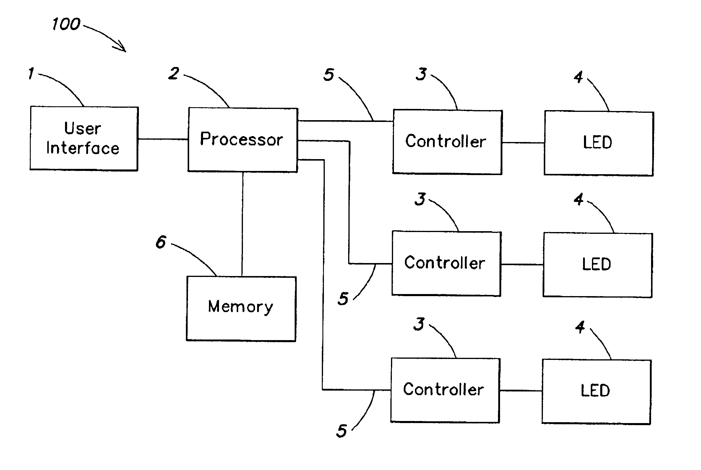
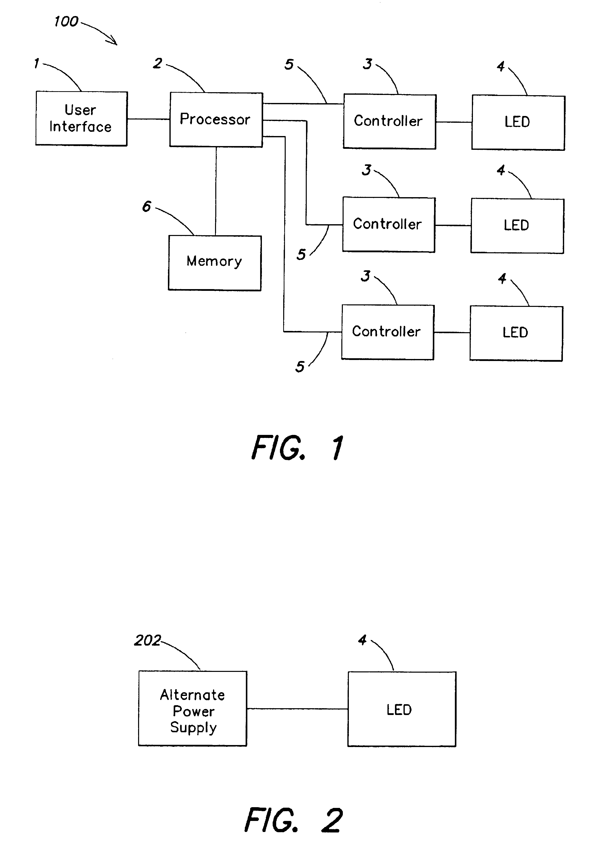
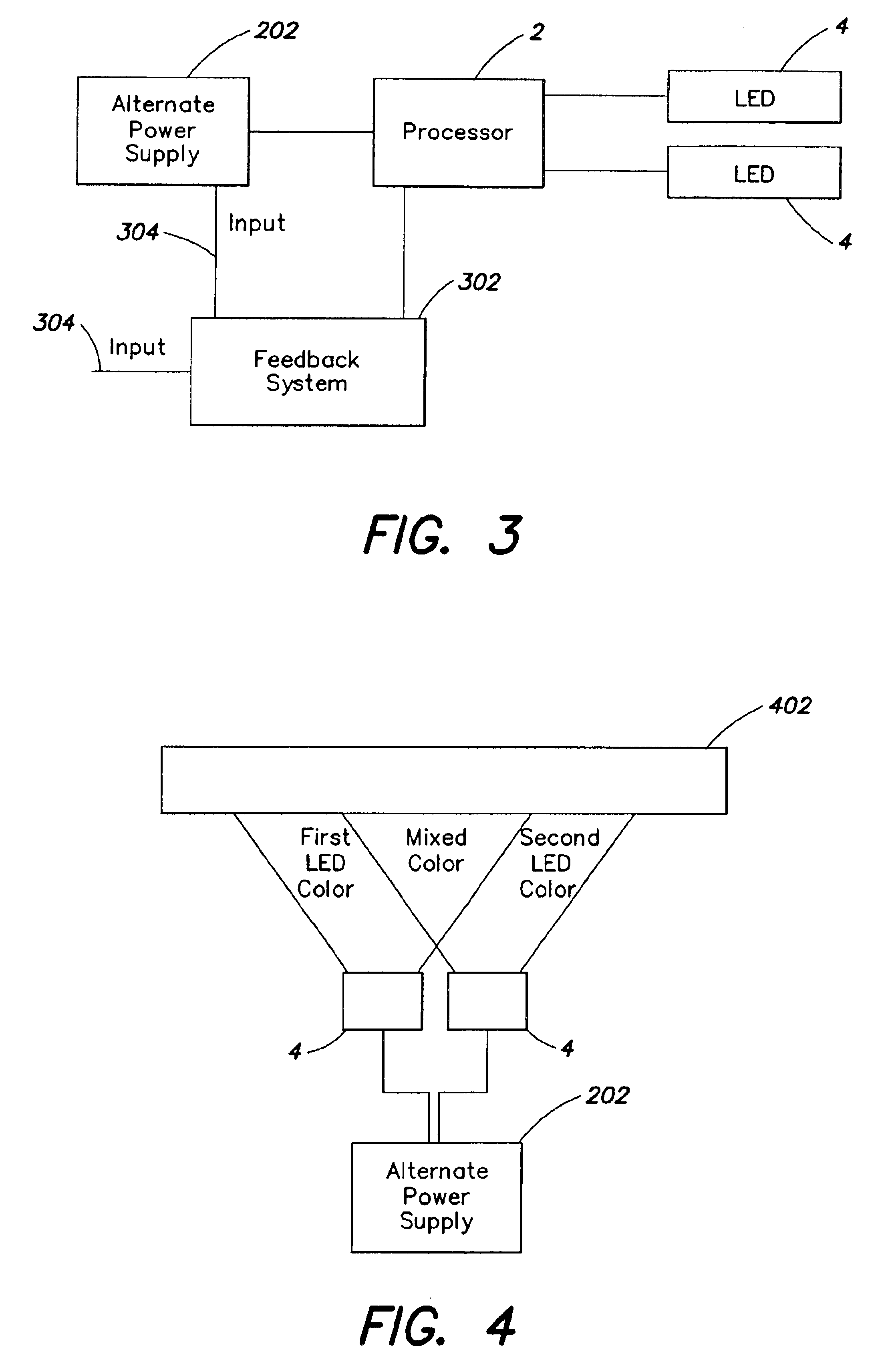
[0018]One embodiment of the present invention generally relates to systems and methods that provide one or more perceptible indications (e.g., illumination, light, sound, warning signals, information signals or the like) through the use of alternative energy generation (e.g. Seebeck power generation). For example, a system according to one embodiment of the present invention may comprise one or more indicators in electrical association with a Seebeck power generator. The electrical association may be such that the one or more indicators become energized when the Seebeck power generator generates sufficient electrical power. In on...
PUM
 Abstract
Description
Claims
Application Information