Method for starting a brushless d.c. motor

a brushless d.c. motor and motor start technology, applied in the direction of motor/generator/converter stopper, electronic commutator, dynamo-electric converter control, etc., can solve problems such as difficult motor start-up

Inactive Publication Date: 2005-04-26
ROBERT BOSCH GMBH
View PDF12 Cites 56 Cited by
  • Summary
  • Abstract
  • Description
  • Claims
  • Application Information

AI Technical Summary

Problems solved by technology

Disadvantageous in this is that no voltage is induced in a motor standstill, the rotor position is not known as a result and therefore motor start-up turns out to be difficult particularly in the case of extremely variable or high loads.

Method used


Image

  • Method for starting a brushless d.c. motor
  • Method for starting a brushless d.c. motor
  • Method for starting a brushless d.c. motor

Examples


Embodiment Construction

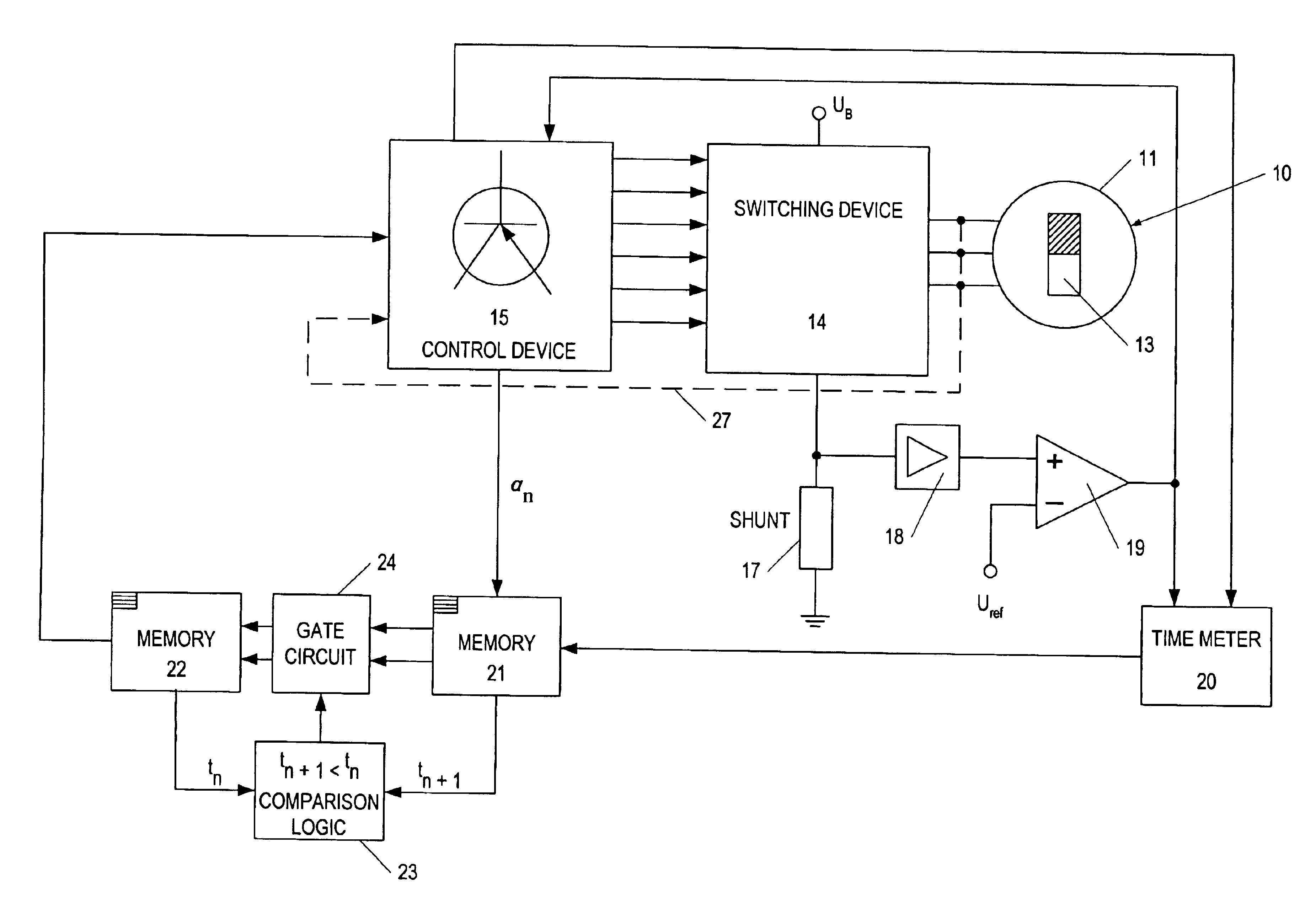
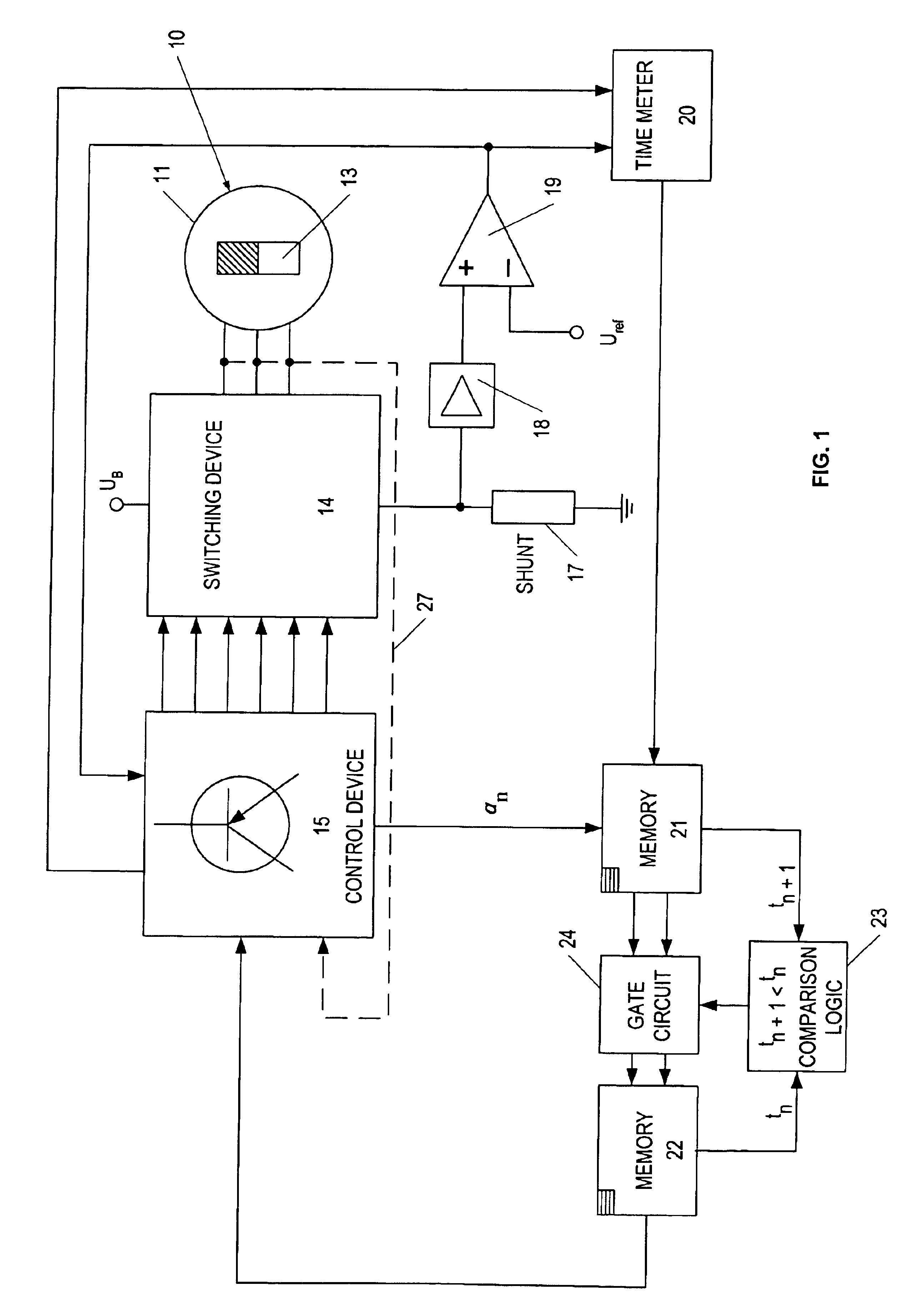
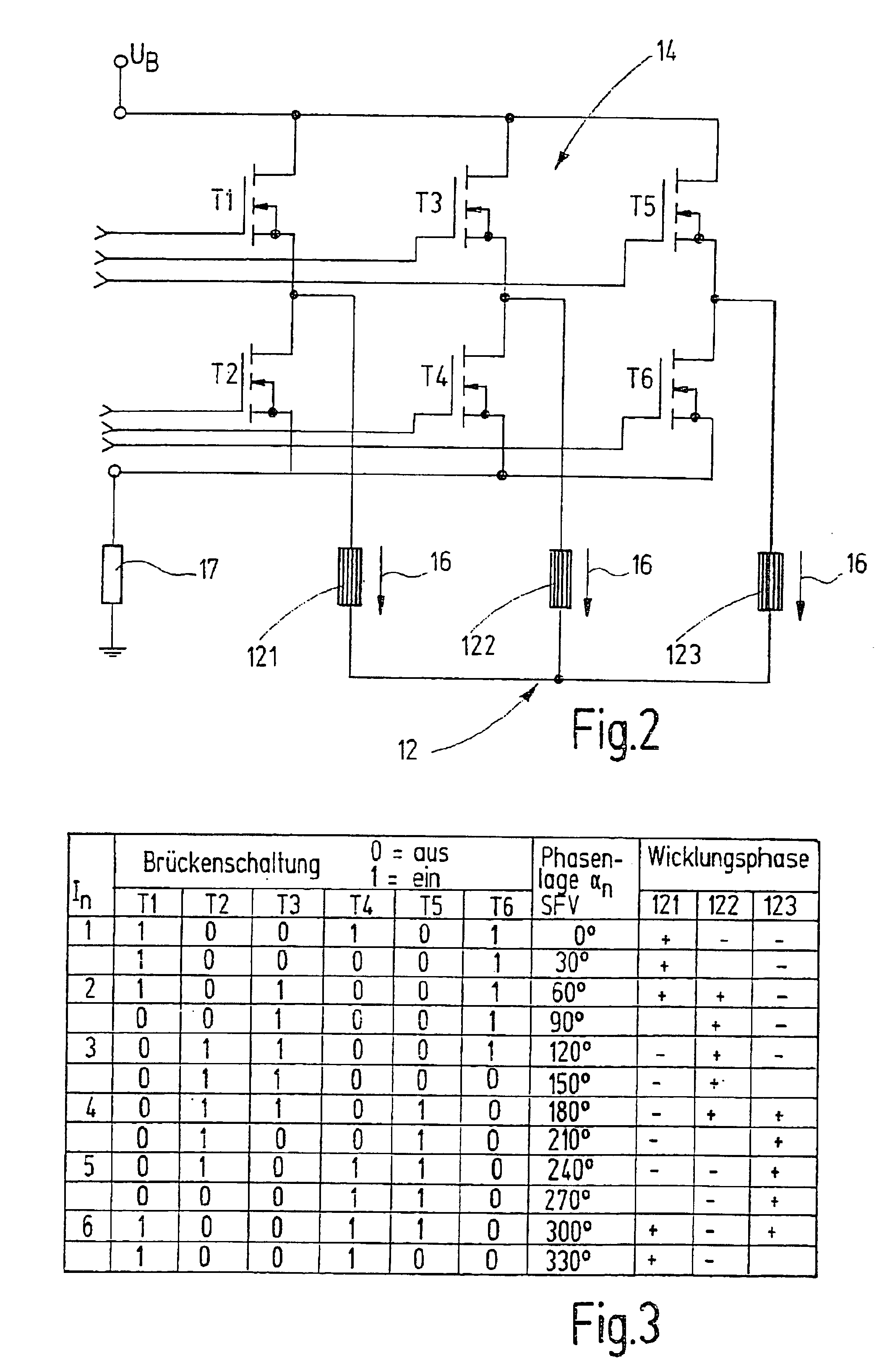
[0017]FIG. 1 depicts a block diagram of a device to operate a brushless direct current motor 10 on a direct current voltage network with mains direct current UB. The direct current motor 10 features in a known manner a stator 11 with a three-phase stator winding 12 in the exemplary embodiment (FIG. 2) and a rotor 13 excited by a permanent magnet. Alternatively, the rotor can also be excited by direct current. The three winding phases or winding strands 121, 122, 123 of the three-phase stator winding 12 are logically so energized by means of a switching device 14, which is controlled by a control device 15, so that a stator field revolves in the stator, which leads the rotor's 13 magnetomotive force by 90° electrically in the direction of rotation. In this process, it is necessary to monitor the rotational position of the rotor 13 and to correspondingly trigger the switching device 14. The momentary rotational position of the rotor is determined with the aid of rotor-induced voltage ...


PUM


Abstract

A process to start a brushless direct current motor with a multiphase stator winding is disclosed, in which, during rotor standstill, a plurality of current impulses is intruded on the stator winding, the current rise time until a current threshold is reached is measured in the stator winding with every current impulse and the rotor position is derived from the measured current rise times. A more precise determination of rotor position is achieved with lower control-related effort for a regulated sensorless start-up in that a plurality of test current impulses is successively intruded on the stator winding in such a way that the test current impulses generate stator flow vectors offset by the same angular increments over 360° electrically in the stator. The current rise time for each stator flow vector is measured in the total current of the stator winding and the phase position of the stator flow vector with the smallest current rise time is determined as the rotor position.

Description

STATE OF THE ART[0001]The invention relates to a process to start a brushless direct current motor.[0002]Brushless direct current motors, so-called BLDC motors, are electronically commutated, whereby the switching device's semiconductor switches that are arranged in the bridge circuit are switched through (closed) or blocked (open) according to a prescribed commutation pattern for logically energizing the individual winding strands or winding phases of the stator winding by a control device as a function of the rotational position of the rotor. The commutation guarantees that the angular relation of 90° is electrically maintained between a stator flow vector generated by the stator winding and the rotor's magnetomotive force vector, and thus the rotor is driven by the revolving stator field or stator flow vector.[0003]Position sensors are used in order to determine the rotor position (DE 40 40 926 C1). BLDC motors are known in which rotor-induced voltages are evaluated in order to d...

Claims


Application Information

Patent Timeline
Patent Type & Authority Patents(United States)
IPC IPC(8): H02P6/00H02P6/22H02P6/18H02P6/14H02P6/185
CPCH02P6/22H02P6/185
Inventor HEIDRICH, TORSTEN
Owner ROBERT BOSCH GMBH
Why Eureka
Try Eureka