Hysteretic current mode control converter with low, medium and high current thresholds

Active Publication Date: 2014-08-07
MICROSEMI
View PDF8 Cites 58 Cited by
  • Summary
  • Abstract
  • Description
  • Claims
  • Application Information

AI Technical Summary

Benefits of technology

[0019]Accordingly, it is a principal object of the present invention to overcome the disadvantages of prior art port current control circuits. Particularly, in one embodiment, a hysteretic current mode control converter is provided, the converter constituted of: an inductor; a plurality of electronically controlled switches; and a control circuitry arranged to operate in a buck-boost mode responsive to the output voltage of the converter being within a first predetermined range of the input voltage of the converter, the control circuitry arranged in the buck-boost mode: responsive to a current flowing through the inductor being lower than a predetermined low current threshold, to control the switches to couple the inductor between the

Problems solved by technology

In spite of these advantages, no straightforward design or analysis of HCMC is available which makes it more difficult to use this mode of control.
However, this method does not provide accurate control since the resultant switching

Method used


Image

  • Hysteretic current mode control converter with low, medium and high current thresholds
  • Hysteretic current mode control converter with low, medium and high current thresholds
  • Hysteretic current mode control converter with low, medium and high current thresholds

Examples


Embodiment Construction

[0036]Before explaining at least one embodiment of the invention in detail, it is to be understood that the invention is not limited in its application to the details of construction and the arrangement of the components set forth in the following description or illustrated in the drawings. The invention is applicable to other embodiments or of being practiced or carried out in various ways. Also, it is to be understood that the phraseology and terminology employed herein is for the purpose of description and should not be regarded as limiting.

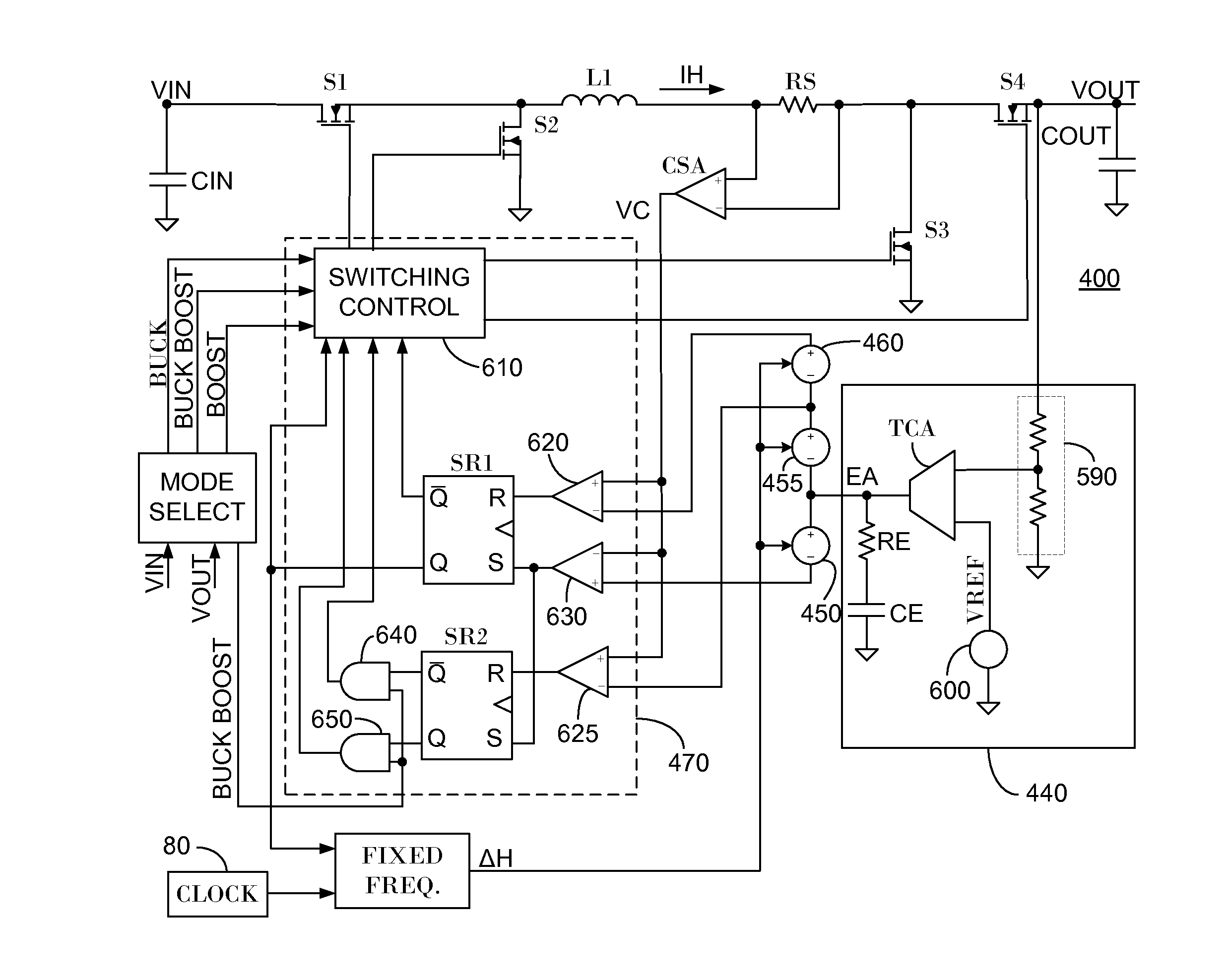
[0037]FIG. 3 illustrates a high level schematic diagram of a hysteretic current mode control converter 300, according to certain embodiments. Converter 300 comprises: a control circuitry 310; an input capacitor CIN; a first electronically controlled switch S1; a second electronically controlled switch S2; a third electronically controlled switch S3; a fourth electronically controlled switch S4; an inductor L1; a sense resistor RS; an output ca...


PUM


Abstract

A converter constituted of: an inductor; a plurality of electronically controlled switches; and a control circuitry arranged to operate in a buck-boost mode responsive to the output voltage of the converter being within a predetermined range of the input voltage of the converter, the control circuitry arranged in the buck-boost mode: responsive to a current flowing through the inductor being lower than a predetermined low current threshold, to control the switches to couple the inductor between the input voltage and a common potential; responsive to the current flowing through the inductor being greater than a predetermined medium current threshold, to control the switches to couple the inductor between the input voltage and the output voltage; and responsive to the current flowing through the inductor being greater than a predetermined high current threshold, to control the switches to couple the inductor between the output voltage and the common potential.

Description

TECHNICAL FIELD[0001]The invention relates generally to the field of hysteretic current mode control of DC / DC converter.BACKGROUND[0002]Presently the most popular methods of control for DC / DC converters are voltage mode control and current mode control. Such controls may be used with hysteretic converters, and a current mode control for hysteretic converter is described=in U.S. Pat. No. 4,494,074 to Bose, granted Jan. 15, 1985 and entitled “FEEDBACK CONTROL”, the entire contents of which are incorporated herein by reference. Despite this description, hysteretic current mode control remains an obscure technique that few designers use, yet offers advantages in some applications. Hysteretic current mode control (HCMC) offers the tightest and most accurate control of inductor current, and offers excellent transient response to step loads. The advantages of this control technique include: inherent load current limiting; no slope compensation required for duty cycles above 50%; easy loop ...

Claims


Application Information

Patent Timeline
IPC IPC(8): H02M3/158
CPCH02M3/1582G05F1/10
Inventor PEKER, ARKADIYSMITH, JR., KEVIN MARKKORCHARZ, DROR
Owner MICROSEMI
Why Eureka
Try Eureka