Band-pass filter using film bulk acoustic resonator

a band-pass filter and bulk acoustic resonator technology, applied in the field of communication devices, can solve the problems of poor stop band attenuation characteristics, insufficient attenuation characteristics, and deterioration of characteristics in insertion loss, so as to improve the attenuation characteristics of stop bands, improve the size of the whole filter, and improve the effect of stopping band attenuation characteristics

Active Publication Date: 2005-04-26
MEMS SOLUTIONS INC
View PDF7 Cites 115 Cited by
  • Summary
  • Abstract
  • Description
  • Claims
  • Application Information

AI Technical Summary

Benefits of technology

[0013]According to the present invention, it is possible to provide a filter in which stop band attenuation characteristics

Problems solved by technology

However, the conventional ladder-type filters tend to indicate poor stop band attenuation characteristics.
That is, there is a problem that the attenuation characteristics are not sufficient in a stop band having a frequency higher or lower tha

Method used


Image

  • Band-pass filter using film bulk acoustic resonator
  • Band-pass filter using film bulk acoustic resonator
  • Band-pass filter using film bulk acoustic resonator

Examples


example 1

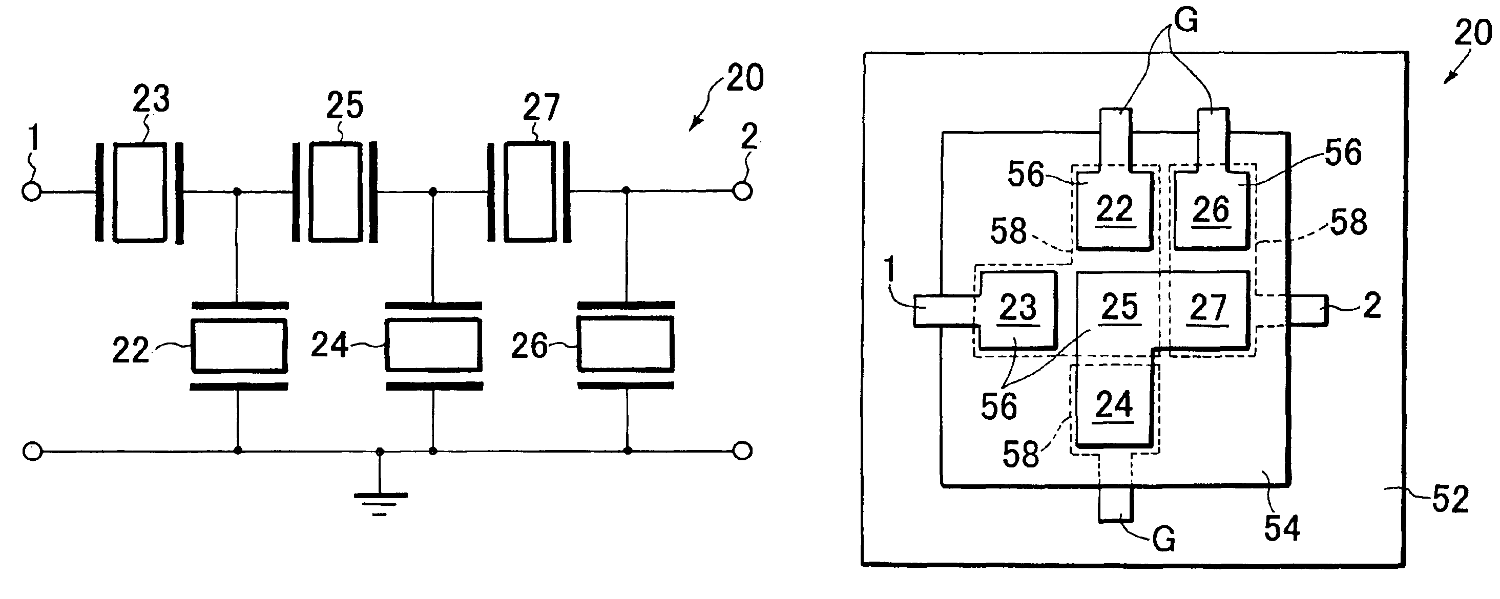
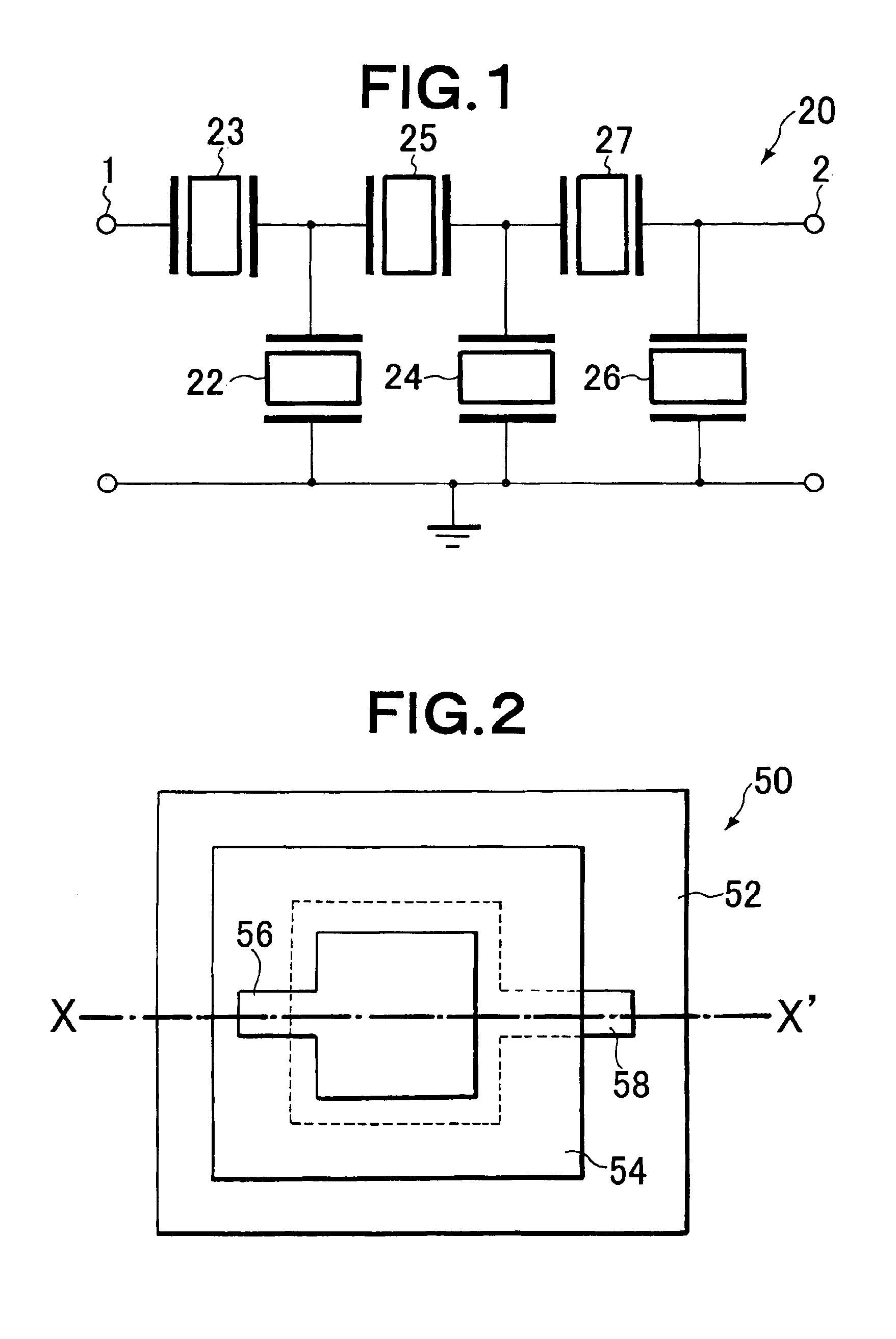
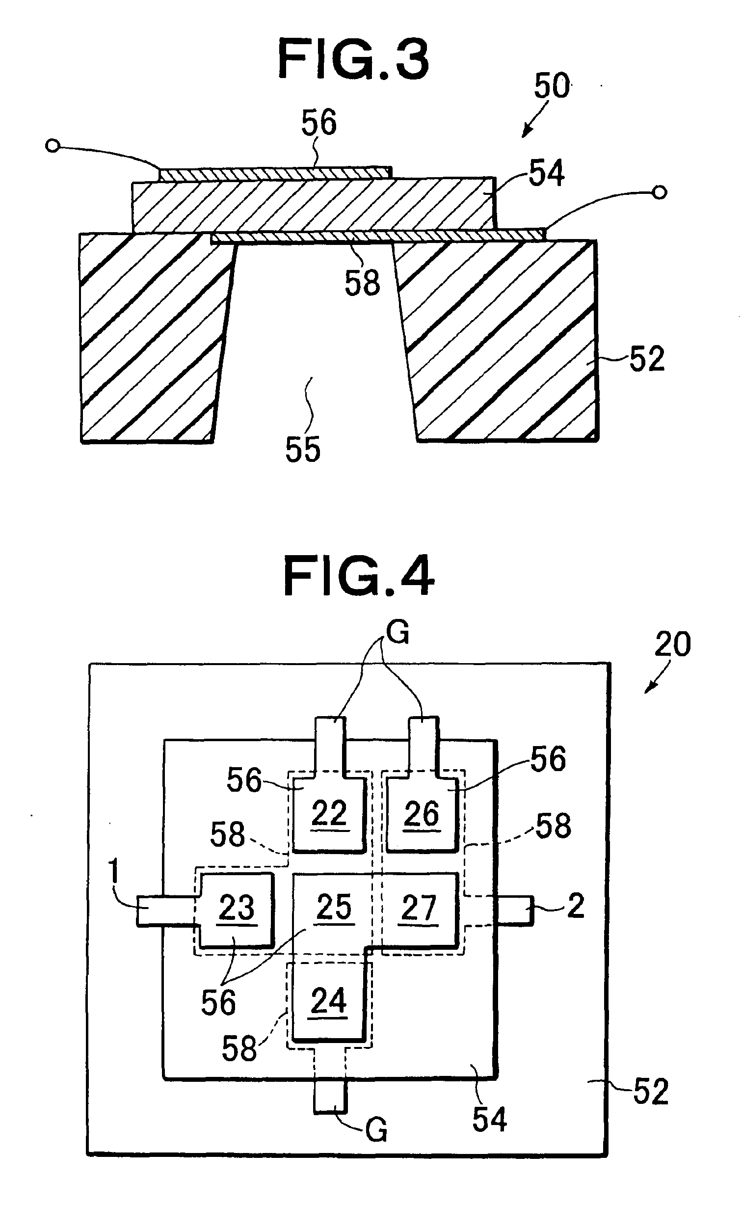
[0046]The materials and thicknesses of the constituting members were set as described in Table 1 to form the ladder-type filter constituted of six FBARs shown in FIG. 1 including FBAR configured as shown in FIG. 3. That is, the characteristic impedance Z1 of one of the series elements was set to 70Ω which was larger than the characteristic impedance Z0 (50Ω herein) of the first and second terminals. The characteristic impedance Z2 of one of the shunt elements was set to 35Ω which was smaller than the characteristic impedance Z0 (50Ω herein) of the first and second terminals. A frequency response of this filter is shown in FIG. 5. When the characteristic impedances of the series and shunt elements were set in a specified range, it was possible to obtain the band-pass filter superior in the stop band attenuation characteristics as shown in FIG. 5. It is seen that the improvement of the stop band attenuation characteristics by 10 dB or more is obtained as compared with Comparative Exam...

example 2

[0048]The materials and thicknesses of the constituting members were set as described in Table 2 to form the ladder-type filter constituted of six FBARs shown in FIG. 1 including FBAR configured as shown in FIG. 3. That is, the characteristic impedance Z1 of one of the series elements was set to 95Ω which was larger than the characteristic impedance Z0 (50Ω herein) of the first and second terminals. The characteristic impedance Z2 of one of the shunt elements was set to 28Ω which was smaller than the characteristic impedance Z0 (50Ω herein) of the first and second terminals. Furthermore, to adjust the pass frequency band width, the thickness of the adjustment electrode of one (element 24) of the shunt elements.

[0049]Accordingly, it was possible to obtain substantially the same frequency characteristics as those shown in Example 1.

[0050]

TABLE 2Series element film bulk acoustic resonatorShunt element film bulk acoustic resonator(23, 25, 27)(22, 24, 26)ThicknessThicknessLayer232527Laye...


PUM


Abstract

A band-pass filter has a ladder-type circuit including first and second terminals whose characteristic impedances are Z0, and series elements and shunt elements disposed between a first terminal and a second terminal, each of the series elements and shunt elements containing a film bulk acoustic resonator. Assuming that characteristic impedance of any one of the series elements is Z1 and that characteristic impedance of any one of the shunt elements is Z2, the characteristic impedances Z0, Z1, and Z2 have a relation of 1<(Z1/Z0)<2, preferably 1.3<(Z1/Z0)<1.7, and 0.5<(Z2/Z0)<1, preferably 0.6<(Z2/Z0)<0.8.

Description

[0001]This application claims priority benefits from Japanese Patent Application No. 2002-321210 filed Nov. 5, 2002.BACKGROUND OF THE INVENTION[0002]1. Field of the Invention[0003]The present invention relates to a technical field of a communication apparatus, particularly to a band-pass filter in which a film bulk acoustic resonator is used.[0004]2. Description of the Related Art[0005]There has been a filter using a film bulk acoustic resonator (FBAR) or thin-film piezoelectric resonator as a filter which can be used in a small size and at a high frequency. A representative equivalent circuit of the film bulk acoustic resonator is shown in FIG. 8. As seen from FIG. 8, one film bulk acoustic resonator includes series resonance portion and parallel resonance portion in the same manner as a SAW resonator. As a general method of using this resonator to constitute the filter, there is a ladder-type filter (e.g., see JP(A)-11-88111 (page 5, FIG. 18)). A frequency response of the ladder-t...

Claims


Application Information

Patent Timeline
IPC IPC(8): H03H9/00H03H9/56H03H9/58H03H9/17
CPCH03H9/564H03H9/568H03H2003/0457
Inventor NISHIMURA, KOSUKEFUJINAGA, MASATAKAKONDO, MASAHIDE
Owner MEMS SOLUTIONS INC
Why Eureka
Try Eureka