Thin film bulk acoustic resonator, method for producing the same, filter, composite electronic component device, and communication device

a resonator and thin film technology, applied in the direction of electrical equipment, impedence networks, etc., can solve the problems of deteriorating frequency characteristics, affecting the performance of the lateral propagation mode, and requiring a complicated production process, so as to achieve the effect of suppressing lateral propagation modes, and reducing the cost of production

Inactive Publication Date: 2007-06-12
PANASONIC CORP
View PDF8 Cites 59 Cited by
  • Summary
  • Abstract
  • Description
  • Claims
  • Application Information

AI Technical Summary

Benefits of technology

[0015]Therefore, an object of the present invention is to provide an improved thin film bulk acoustic resonator which can efficiently suppress lateral propagation modes, without requiring a complicated production process or sacrificing design freedom. Another object of the present invention is to provide a method for producing such a thin film bulk acoustic resonator. Yet another object of the present invention is to provide an improved filter which provides excellent filter characteristics by incorporating such a thin film bulk acoustic resonator. Yet another object of the present invention is to provide a composite electronic component device comprising such a filter. Still another object of the present invention is to provide a communication device comprising such a filter.

Problems solved by technology

These lateral propagation modes are unwanted vibration modes.
In the case of a device including a plurality of adjoining thin film bulk acoustic resonators, the unwanted vibration modes interfere between adjoining thin film bulk acoustic resonators, and thus the unwanted vibration modes similarly contribute to spurious response.
However, in the conventional thin film bulk acoustic resonator disclosed in Japanese Laid-Open Patent No. 2000-31552, it is necessary to additionally provide the acoustic damping material 7, which complicates the production process.
Furthermore, the conventional thin film bulk acoustic resonator also has a problem in that not only the unwanted vibration modes but a portion of the desired vibration mode is also damped, thus resulting in deteriorated frequency characteristics.
This problematically reduces the design freedom.
Specifically, when the thin film bulk acoustic resonator needs to be subjected to integration, it is difficult to obtain a high degree of integration.
The unwanted vibration modes are not completely reflected at the ends of the electrodes but rather are leaked and propagated, thus unfavorably affecting an adjoining resonator.

Method used


Image

  • Thin film bulk acoustic resonator, method for producing the same, filter, composite electronic component device, and communication device
  • Thin film bulk acoustic resonator, method for producing the same, filter, composite electronic component device, and communication device
  • Thin film bulk acoustic resonator, method for producing the same, filter, composite electronic component device, and communication device

Examples


first embodiment

[0087](First Embodiment)

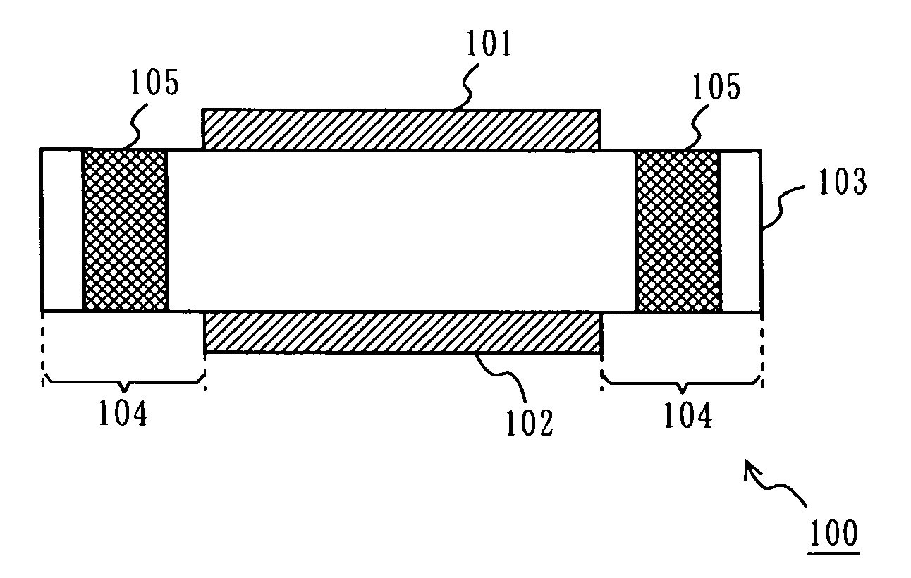
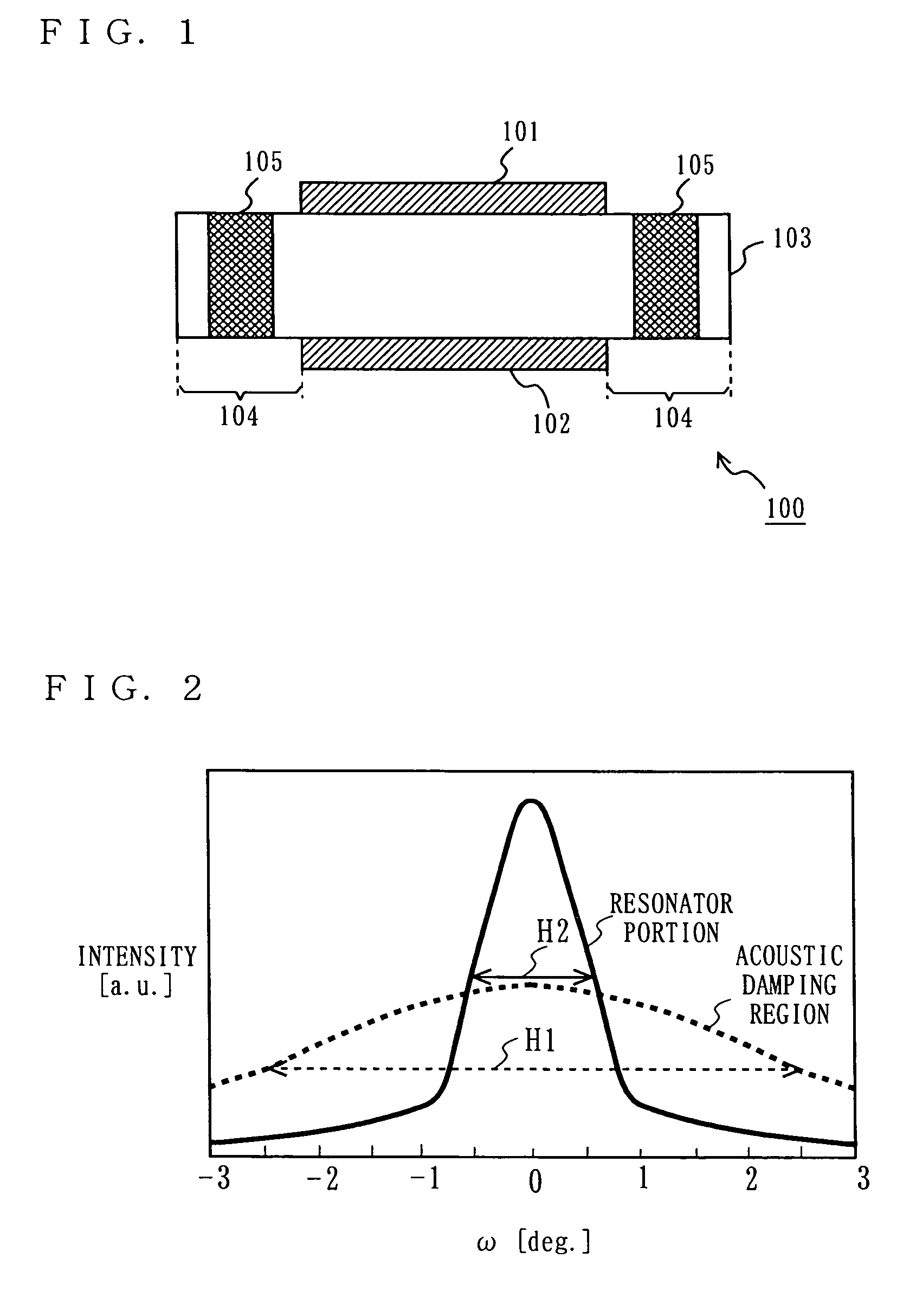
[0088]FIG. 1 is a cross-sectional view showing a thin film bulk acoustic resonator 100 according to a first embodiment of the present invention. Referring to FIG. 1, the thin film bulk acoustic resonator 100 comprises an upper electrode 101, a lower electrode 102, and a piezoelectric film 103. The piezoelectric film 103 includes outer regions 104 which extend outward from the periphery of a resonator portion which is constructed in a region interposed by the pair of electrodes (i.e., the upper and lower electrodes 101 and 102). Each outer region 104 includes, in a portion thereof, an acoustic damping region 105 for damping acoustic waves from the resonator portion.

[0089]The piezoelectric film 103 is composed of a suitable piezoelectric material such as zinc oxide (ZnO), lead zirconate titanate (PZT), aluminum nitride (AlN), or the like.

[0090]The upper electrode 101 and the lower electrode 102 are composed of a suitable material such as molybdenum (Mo), tungst...

second embodiment

[0104](Second Embodiment)

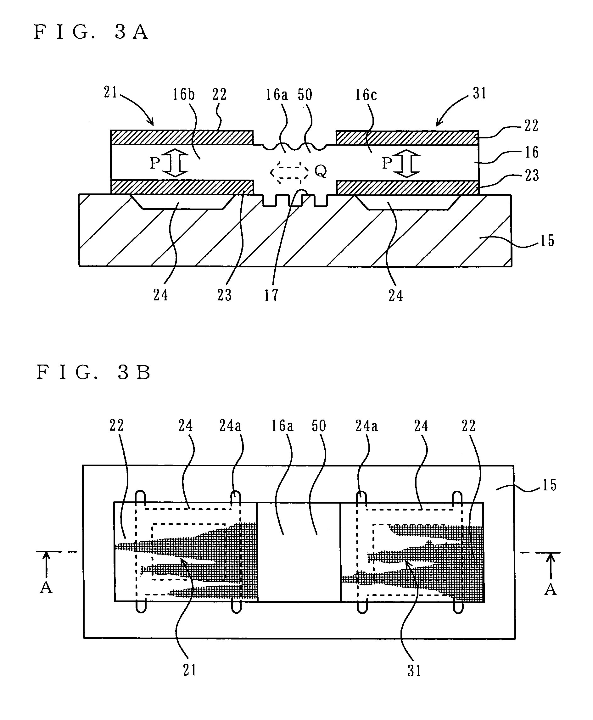
[0105]FIG. 3A is a cross-sectional view showing a thin film bulk acoustic resonator according to a second embodiment of the present invention. FIG. 3B is an upper plan view showing the thin film bulk acoustic resonator according to the second embodiment of the present invention. FIG. 3A provides a cross-sectional view taken along line A—A in FIG. 3B.

[0106]Referring to FIGS. 3A and 3B, the thin film bulk acoustic resonator according to the second embodiment comprises a first thin film bulk acoustic resonator 21, a second thin film bulk acoustic resonator 31, an acoustic damping region 50, and a substrate 15. On the upper face of the substrate 15, two cavities 24 are provided corresponding to the first and second thin film bulk acoustic resonators 21 and 31, respectively. Corresponding to the first and second thin film bulk acoustic resonators 21 and 31, respectively, two lower electrodes 23 are provided so as to cover the two cavities 24. On the substrate 15,...

third embodiment

[0127](Third Embodiment)

[0128]FIG. 5 is a cross-sectional view showing a thin film bulk acoustic resonator according to a third embodiment of the present invention. In FIG. 5, any portion which is similar or corresponds to a counterpart in the thin film bulk acoustic resonator as shown in FIGS. 3A and 3B is denoted by the same reference numeral as that used in FIGS. 3A and 3B, and the descriptions thereof are omitted.

[0129]As shown in FIG. 5, in the third embodiment, cavities 24b are formed so as to penetrate through the substrate 15a. Thus, even in the case where the cavities are not only formed in the surface of the substrate but penetrate through the substrate, similar effects to those described above can be obtained.

[0130]According to the producing method shown in FIGS. 4A to 4G, it is necessary to first embed a sacrificial layer 25 in each cavity 24 formed in the surface of the substrate 15, form lower electrodes 23, a piezoelectric film 16, upper electrodes 22 on the sacrifici...


PUM


Abstract

A thin film bulk acoustic resonator includes a piezoelectric film, and a pair of electrodes between which the piezoelectric film is interposed. The piezoelectric film includes an outer region extending outwards from at least a portion of the periphery of a resonator portion composed of the pair of electrodes and the piezoelectric film. The outer region includes, in at least a portion thereof, an acoustic damping region for damping acoustic waves.

Description

BACKGROUND OF THE INVENTION[0001]1. Field of the Invention[0002]The present invention relates to a thin film bulk acoustic resonator, and more particularly to an improved thin film bulk acoustic resonator which effectively suppresses spurious response and which provides excellent frequency characteristics. The present also relates to a method for producing such a thin film bulk acoustic resonator. The present also relates to an improved filter which provides excellent filter characteristics by incorporating such a thin film bulk acoustic resonator. The present also relates to a composite electronic component device comprising such a filter. The present also relates to a communication device comprising such a filter and a composite electronic component device.[0003]2. Description of the Background Art[0004]Component elements to be internalized in an electronic device such as a mobile device are required to be reduced in size and weight. For example, a filter to be used in a mobile de...

Claims


Application Information

Patent Timeline
Patent Type & Authority Patents(United States)
IPC IPC(8): H03H9/00H03H9/09H03H3/02H03H9/13H03H9/17H03H9/56
CPCH03H3/02H03H9/02118H03H9/171H03H9/564H03H9/568
Inventor ONISHI, KEIJINAKAMURA, HIROYUKINAKATSUKA, HIROSHIYAMAKAWA, TAKEHIKO
Owner PANASONIC CORP
Why Eureka
Try Eureka