Water heater apparatus and associated manufacturing and insulation methods

Active Publication Date: 2005-04-26
RHEEM MFG CO
View PDF10 Cites 17 Cited by
  • Summary
  • Abstract
  • Description
  • Claims
  • Application Information

AI Technical Summary

Benefits of technology

[0010]After the first insulation quantity has hardened, a second quantity of flowable, hardenable insulation, preferably a liquid foam insulation, is flowed into a second portion of the cavity and into contact with the wall portion of the bag and the hardened insulation protrusions thereon. The second insulation quantity is permitted to harden and become mechanically interlocked with the previously hardened insulation protrusions in a manner substantially preventing shrinkage-created separation of the second insulation quantity from the wall portion of the bag. In this manner, in the finished insulated tank apparatus which also embodies principles of the present invention, there is no appreciable heat loss gap or void between the second batch of insulation and the foam filled bag.
[0012]In accordance with another aspect of the present invention, the bag has an essentially closed upper end with a relatively small inlet opening therein through which the first insulation quantity is injected into the bag. Small insulation vent openings are formed in the bag adjacent this injection inlet opening. Because of this configurational aspect of the bag, insulation injected into the bag is pressure-packed into the bag, as opposed to being permitted to merely “free rise” therein. This results in a desirably increased hardened insulation density uniformity along the vertical dimension of the bag. According to a further aspect of the present invention, this vertical insulation density uniformity is additionally enhanced by arranging the metering openings vertically along opposite vertical side edge portions of the bag and configuring the metering openings in a manner such that their cross-sectional areas increase in an upward direction along such side edge portions of the bag.

Problems solved by technology

Several well known problems, limitations and disadvantages are typically associated with this conventional plastic bag-based foam dam construction.
First, after the second or main batch of foamed-in insulation hardens it tends to pull away from the plastic bag in a manner creating a gap between the second foam batch and the bag along the entire length of the water heater.
This gap, caused by shrinkage of the second foam batch, undesirably permits appreciable heat loss from the tank therethrough.
This results in an undesirably decreased foam density in a top portion of the bag, resulting in a lesser insulation efficiency in the top portion of the bag.
Third, bags of this conventional type are typically of a flat construction, but are used to sealingly fill a three dimensional portion of the tank / jack insulation cavity.

Method used


Image

  • Water heater apparatus and associated manufacturing and insulation methods
  • Water heater apparatus and associated manufacturing and insulation methods
  • Water heater apparatus and associated manufacturing and insulation methods

Examples


Embodiment Construction

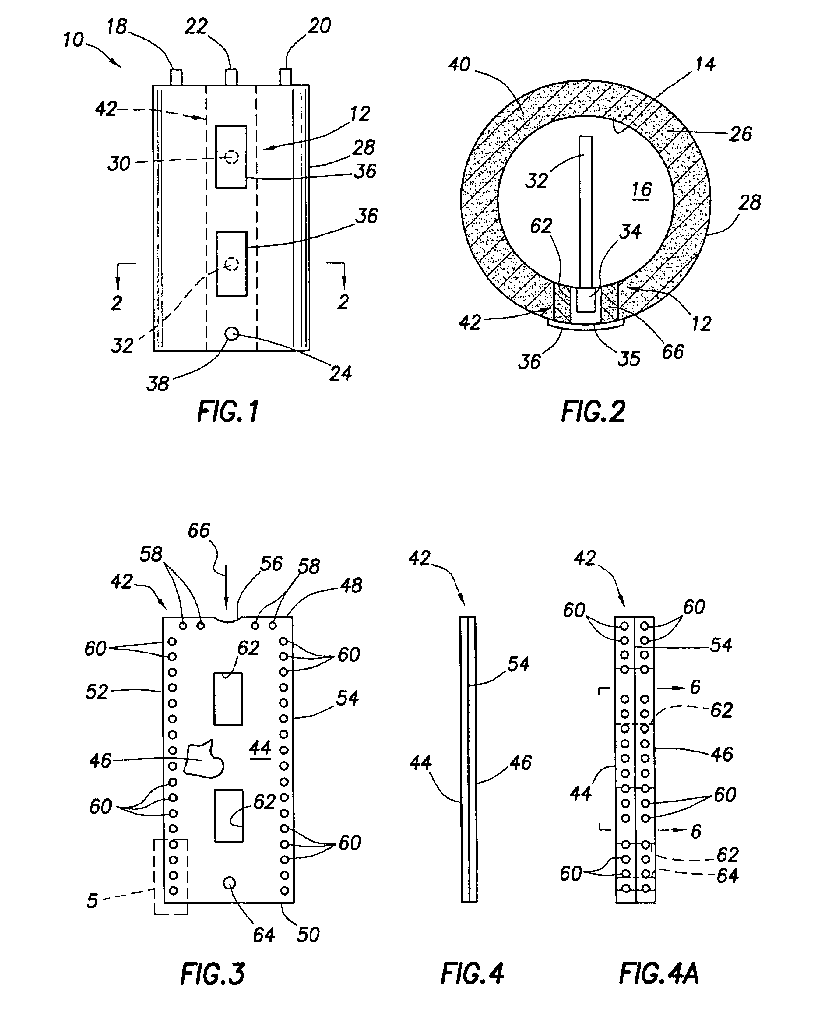
[0026]Referring initially to FIGS. 1 and 2, the present invention provides a water heater, representatively an electric water heater 10, which is constructed and insulated in a unique manner using a specially designed foam dam structure 12 (see FIG. 2) which will be subsequently described herein. Water heater 10 includes a vertically oriented, representatively cylindrical metal storage tank 14 adapted to hold a quantity of pressurized hot water 16 for on-demand delivery to various plumbing fixtures such as sinks, tubs, showers, dishwashers and the like. Extending upwardly from the upper end of the tank 14 are the usual cold water inlet, hot water outlet, and temperature and pressure relief fittings 18,20 and 22. On the side of the tank 12, near its bottom end, is an outwardly projecting drain fitting 24.

[0027]Outwardly circumscribing the tank 14, and forming therewith an insulation cavity 26, is a metal jacket of a suitable, conventional construction. To heat the water 16 within the...


PUM

PropertyMeasurementUnit
Lengthaaaaaaaaaa
Electrical resistanceaaaaaaaaaa
Densityaaaaaaaaaa

Abstract

A foam dam in the insulation cavity of an electric water heater comprises a plastic bag into which liquid foam insulation is injected, the bag having an essentially closed top edge portion with only a small opening for receiving the injected insulation. A small portion of the insulation injected into the bag is forced outwardly therefrom via small metering holes to form external protrusions on the bag that mechanically interlock with a second batch of insulation subsequently injected into the cavity and prevent the hardened second insulation batch from pulling away from the bag. The substantially closed top edge of the bag permits the insulation injected into the bag to pack therein and increase the top-to-bottom hardened foam density uniformity. Side edges of the bag may be pleated to increase the sealing area of the foam dam.

Description

BACKGROUND OF THE INVENTION[0001]The present invention generally relates to the manufacture of insulated structures and, in a preferred embodiment thereof, more particularly relates to water heater structures and associated manufacturing and insulation methods therefor.[0002]A conventional water heater of either the electric or fuel-fired type normally comprises a water storage tank, typically of a metal construction, adapted to hold a quantity of pressurized, heated water for on-demand delivery to various plumbing fixtures such as sinks, tubs, showers, dishwashers or the like. Outwardly surrounding the tank is a jacket, typically of a metal construction, which defines around the tank a cavity which is filled with a suitable insulation material, usually a hardened foam insulation material which is initially injected into the cavity in liquid form during the fabrication of the water heater. Various control structures, such as thermostats and electric heating element structures projec...

Claims


Application Information

Patent Timeline
IPC IPC(8): F24H1/18
CPCF24H1/182B29C44/182B29C44/1247B29K2995/0015
Inventor HICKS, KENNETH J.HENDERSON, DAVID L.BOROS, JOZEF
Owner RHEEM MFG CO
Why Eureka
Try Eureka