Compressor protection from liquid hazards

a technology for compressors and liquids, applied in the direction of machines/engines, positive displacement liquid engines, lighting and heating apparatus, etc., can solve problems such as system failure, and achieve the effect of minimizing liquid hazards

Inactive Publication Date: 2005-05-03
CARRIER CORP
View PDF8 Cites 61 Cited by
  • Summary
  • Abstract
  • Description
  • Claims
  • Application Information

AI Technical Summary

Benefits of technology

[0009]It is a further object of this invention to provide a method for operating a refrigeration or air conditioning system so as to minimize liquid hazards for the accomplished by the present invention.

Problems solved by technology

If insufficient oil is present the system would not be enabled.

Method used


Image

  • Compressor protection from liquid hazards
  • Compressor protection from liquid hazards
  • Compressor protection from liquid hazards

Examples


Embodiment Construction

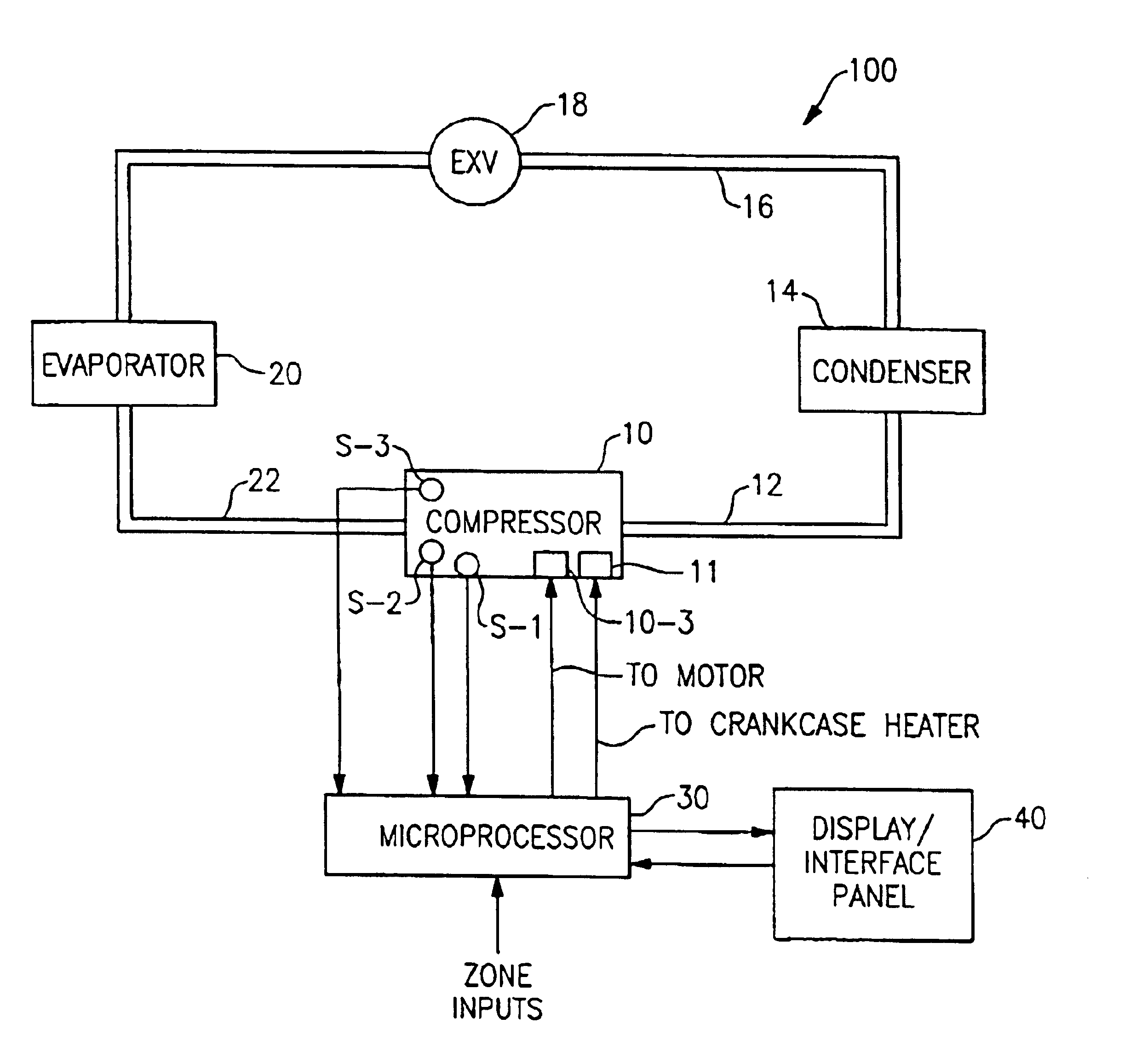
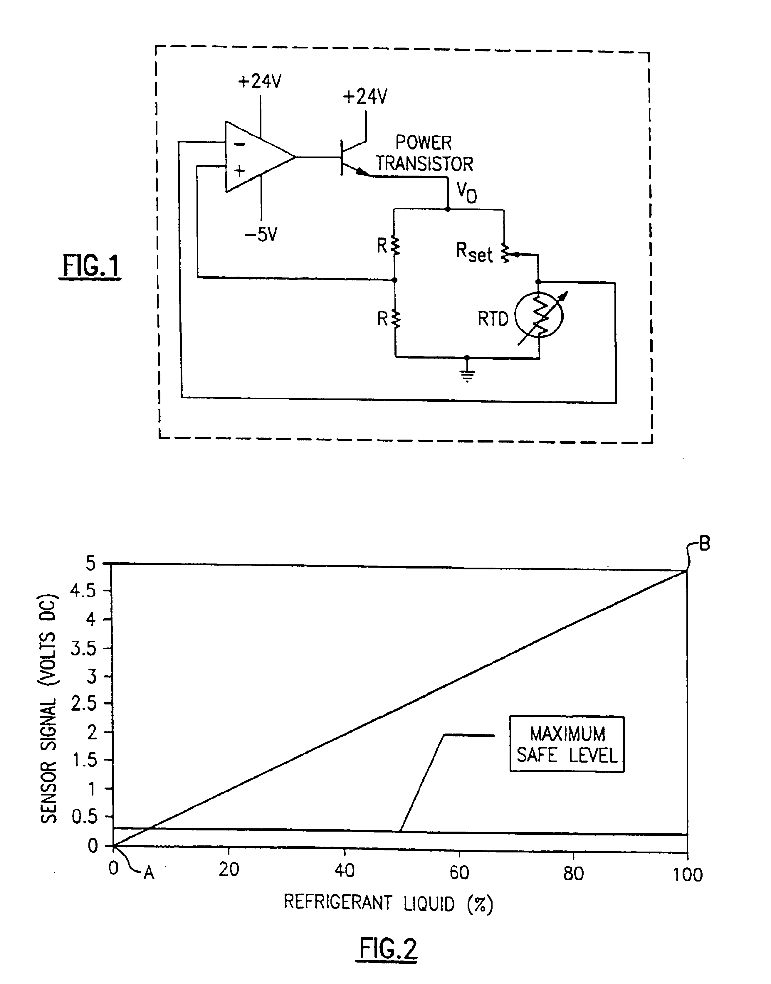
[0021]FIG. 1 corresponds to FIG. 2 of the SAE journal article entitled “A or Estimating the Liquid Mass Fraction of the Refrigerant Exiting an Evaporator” authored by James Solberg, Norman R. Miller and Predrag Hrnjak. The article indicates that the circuit illustrated in FIG. 1“tries to keep the resistance of the” resistance temperature detector, RTD, “equal to Rset” which is the RTD resistance. “The circuit uses an operational amplifier as the medium for feedback. The op-amp uses the feedback to maintain its inputs at constant voltage while drawing very little current. This is what forces the resistance of the RTD to be equal to the resistance of Rset. Traditionally, an RTD is used to measure temperature by measuring the resistance of the RTD as it changes with temperature. But, this circuit forces the resistance of the RTD to be equal to Rset. The circuit compensates by heating up the RTD until the resistance (and thus the temperature) of the RTD is equal to Rset.”
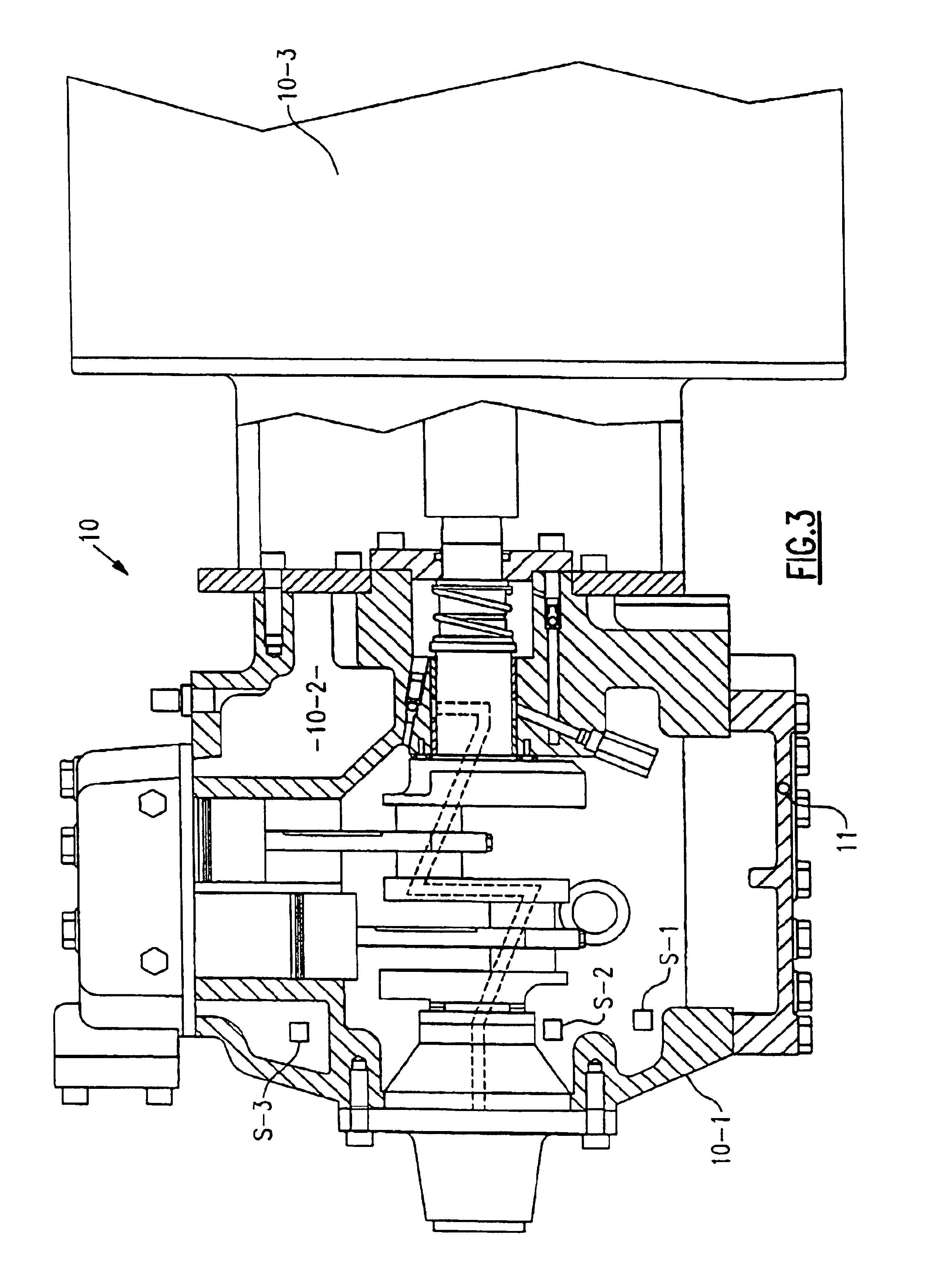
[0022]In operat...


PUM


Abstract

Two liquid levels are sensed in the oil sump of a compressor to determine if sufficient oil and excess refrigerant are present prior to starting the compressor and appropriate steps taken, if necessary. At start-up, and during operation, the presence or flow of liquid refrigerant in the suction of the compressor is sensed and appropriate steps taken, if necessary.

Description

BACKGROUND OF THE INVENTION[0001]In an inactive air conditioning, heat pump, or refrigeration system, pressure equalization takes place and refrigerant tends to condense and collect at cool and / or low locations in the system. For the range of indoor and outdoor temperatures encountered in many systems during the off-portions of their cycles, the compressor is often the coolest part of the system for some period of time. As a result, considerable liquid refrigerant may collect in both suction-side and discharge-side portions of the compressor.[0002]Liquid refrigerant that collects in the compressor oil sump produces a raising of the liquid level but dilutes the oil, reducing its ability to lubricate compressor bearings and other moving parts when the compressor is started. Liquid refrigerant that condenses on the suction side of the compressor may be drawn into the compression mechanism at start-up resulting in a flooded start. Since the liquid is essentially incompressible, its pres...

Claims


Application Information

Patent Timeline
Patent Type & Authority Patents(United States)
IPC IPC(8): F04B39/02F04B49/02F04B49/10F25B31/00F25B49/00
CPCF04B39/0207F04B49/02F04B49/10F25B31/004F25B49/005F25B2700/04F25B2400/01F25B2500/26F25B2500/28F25B2700/03F25B1/02F25B43/00F25B43/02F25B49/02
Inventor DUDLEY, KEVIN F.
Owner CARRIER CORP
Why Eureka
Try Eureka