Estimating formation properties in inter-well regions by monitoring saturation and salinity front arrivals

a technology of saturation and salinity fronts and formation properties, applied in the field of determining effective formation properties in the interwell region, can solve the problems of erroneous predictions of reservoir performance, salinity and saturation fronts, and limited usefulness in the inter-well region, and achieve the effect of more robust appraisal and detailed and improved characterization

Inactive Publication Date: 2005-05-03
SCHLUMBERGER TECH CORP
View PDF17 Cites 53 Cited by
  • Summary
  • Abstract
  • Description
  • Claims
  • Application Information

AI Technical Summary

Benefits of technology

[0010]While tracking the oil-water saturation front allows characterization of the formation, a more detailed and improved characterization is possible, in accordance with the present invention, if the water salinity front movement is also tracked together with the oil-water saturation front in the formation. The salinity front results when the injected water salinity is different from the formation water salinity. Tracking the arrival of both fronts at a monitoring location (such as an observation well or a production well, etc.) will allow estimation of effective properties in the inter-well region (between the origination well and the monitoring well) such as porosity, connate water saturation, residual oil saturation and relative permeability curves. Information for inversion is contained both in the separation of the two fronts as well as in the shape of the water saturation curve as it evolves at the monitoring location over time. Such methods will allow more robust appraisal of the formation.

Problems solved by technology

For heterogeneous reservoirs, such interpolation using sparse local data leads to erroneous predictions of reservoir performance.
Invasion of mud filtrate into the formation during drilling results in salinity and saturation fronts in the near wellbore region.
While the method of the '321 Patent is effective in the near wellbore region, its usefulness is limited in the inter-well region.

Method used


Image

  • Estimating formation properties in inter-well regions by monitoring saturation and salinity front arrivals
  • Estimating formation properties in inter-well regions by monitoring saturation and salinity front arrivals
  • Estimating formation properties in inter-well regions by monitoring saturation and salinity front arrivals

Examples


Embodiment Construction

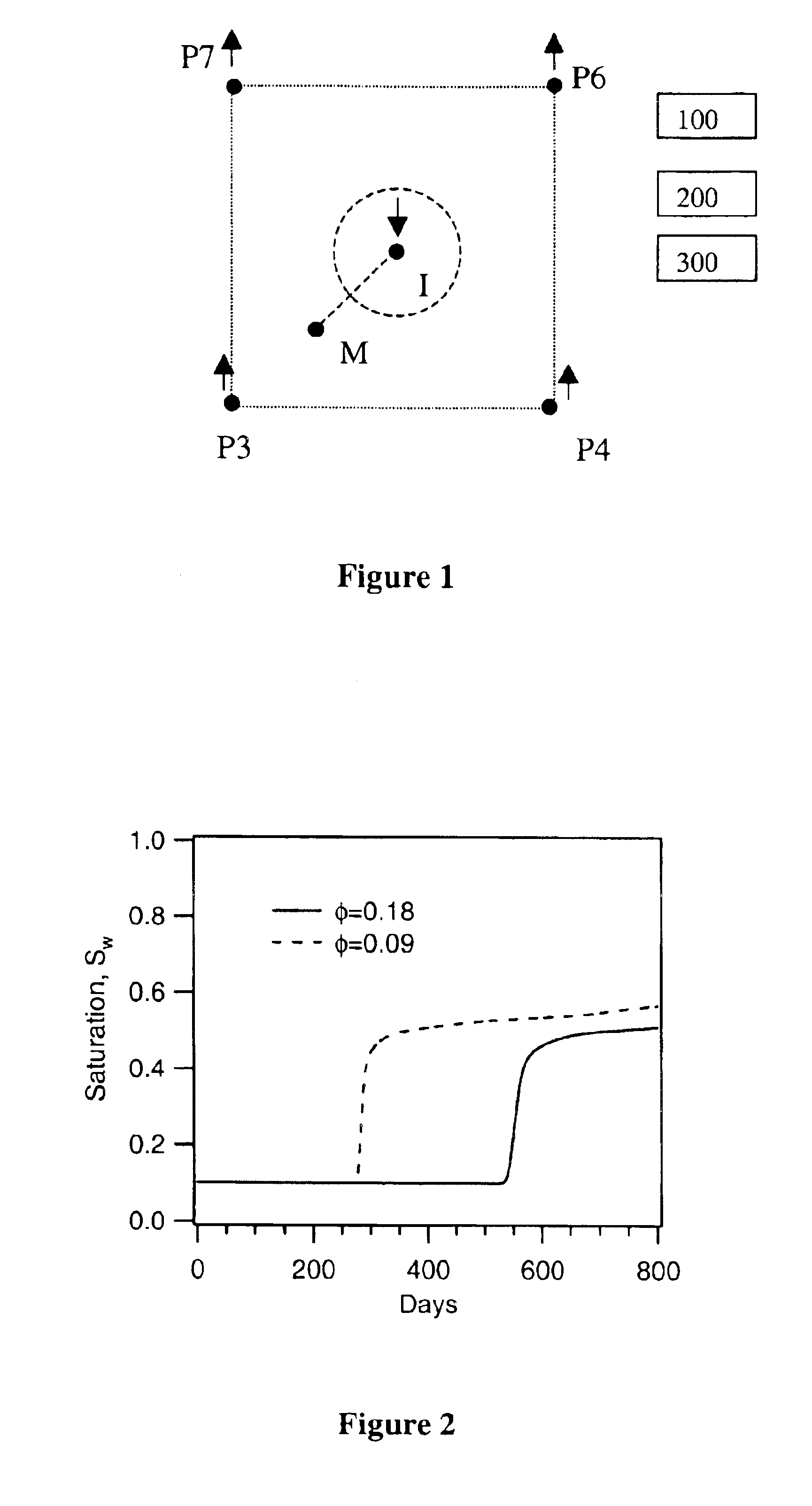
[0025]FIG. 1 diagrams a typical five spot flooding pattern with a 15 foot thick pay zone and a permeability of about 70 mD. This configuration is used to explain the present invention and is intended to be non-limiting. One skilled in the art would recognize that additional configurations may be suitably employed.

[0026]As shown in the non-limiting model configuration of FIG. 1, a monitoring well with a permanently installed resistivity array may be drilled between an injector well (I) and a producer wells (P3, P4, P6 and P7). By way of example, the monitoring well (M) is shown halfway between I and P3; the actual number, type and location of the origination well (i.e. injector) and the monitoring locations may differ depending on the reservoir characteristics. The monitoring location may be an observation well, an appraisal well, a producing well or an exploratory well (or any combination of these wells). Well logs and core analysis at these two wells can give information about the ...


PUM


Abstract

A method and system of monitoring the movement of at least one front in an inter-well region is comprised of: providing a first well representing the origination of at least one front (such as a saturation front or a salinity front); providing one or more monitoring locations, each equipped with at least one sensor; and monitoring the arrival of at least one front at one or more monitoring locations. The origination well may be any type of permanent or temporary well, but is preferably an injector well. Likewise, the monitoring location(s) may be any type of permanent or temporary well such as an observation well, a production well, an exploratory well, and an appraisal well. Information regarding front arrival times may be used to characterize or appraise the formation. Front arrivals may be monitored as a function of time to develop their respective time evolution and shape.

Description

FIELD OF THE INVENTION[0001]The present invention relates to methods for determining effective formation properties in the inter-well region by using measurements from sensors in monitoring locations (i.e., observation wells or producing wells, or other type of well) and, more particularly, to methods for estimating effective porosity, connate water saturation, residual oil saturation and relative permeability curves over inter-well regions of the reservoir by tracking arrival times of oil-water saturation front and salinity front.BACKGROUND OF THE INVENTION[0002]Estimation of formation properties is crucial to successful reservoir production and management. Reservoir simulators typically divide the reservoir into grid blocks and use finite difference techniques to model fluid flow in the reservoir. They require formation property and initial condition input for each grid cell. However, formation properties estimated from log data are valid only in the near wellbore region on the or...

Claims


Application Information

Patent Timeline
Patent Type & Authority Patents(United States)
IPC IPC(8): E21B47/10E21B47/00G01V11/00
CPCE21B47/00G01V11/00E21B47/102E21B47/113E21B49/0875
Inventor RAGHURAMAN, BHAVANIAUZERAIS, FRANCOIS M.
Owner SCHLUMBERGER TECH CORP
Why Eureka
Try Eureka