Surface mount technology evaluation board having varied board pad characteristics

a technology of surface mount and evaluation board, which is applied in the direction of circuit inspection/indentification, final product manufacturing, instruments, etc., can solve the problems of etc., and affecting the quality of the product. , the problem of particular solder paste that is used may not be suitable for adhesion to the board pad on the pcb, and the defect can occur during

Active Publication Date: 2005-05-03
MALIKIE INNOVATIONS LTD
View PDF24 Cites 79 Cited by
  • Summary
  • Abstract
  • Description
  • Claims
  • Application Information

AI Technical Summary

Benefits of technology

[0008]In one aspect, the present invention provides an evaluation board for evaluating one or more aspects of a surface mount technology system, the board comprising: a substrate having a surface; and a plurality of board pad patterns formed on the surface, wherein each of the board pad patterns includes a plurality of board pads.

Problems solved by technology

Manufacturing defects can occur during the solder paste deposition, component placement and reflow stages of the SMT process.
However, typically 60 to 70% of the defects occur during the solder paste deposition stage.
For instance, the particular solder paste that is used may not be suitable for adhering to a board pad on the PCB given the operating conditions used in the solder paste deposition stage or the stencil may be clogged.
Alternatively, there may be too much or too little solder paste that is deposited.
If too little solder paste is deposited, then poor mechanical and / or electrical contact between the board pad and the corresponding component pad may result.
Other defects which may occur includes voids, which are bubbles that are suspended in solidified solder.
This size reduction has stretched the capabilities of screen printing equipment and solder paste and increased the incidence of defects in the SMT manufacturing process.

Method used


Image

  • Surface mount technology evaluation board having varied board pad characteristics
  • Surface mount technology evaluation board having varied board pad characteristics
  • Surface mount technology evaluation board having varied board pad characteristics

Examples


Embodiment Construction

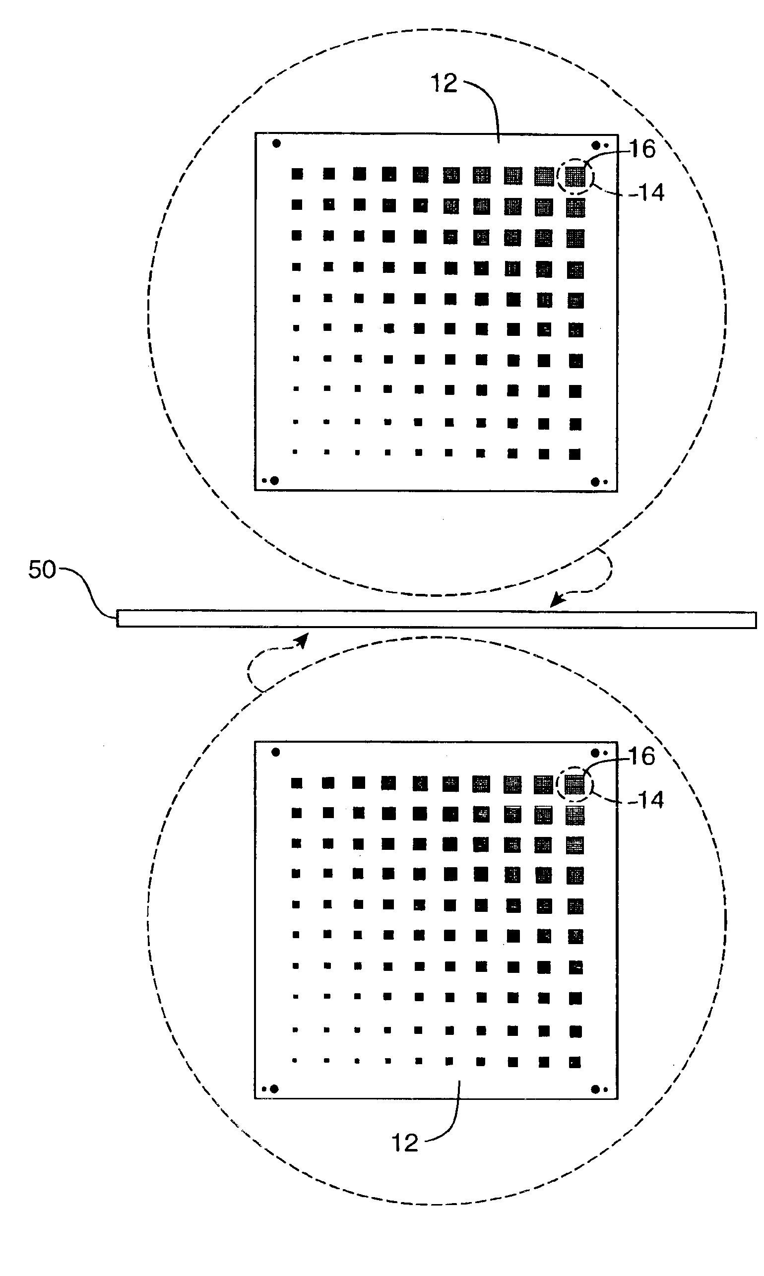
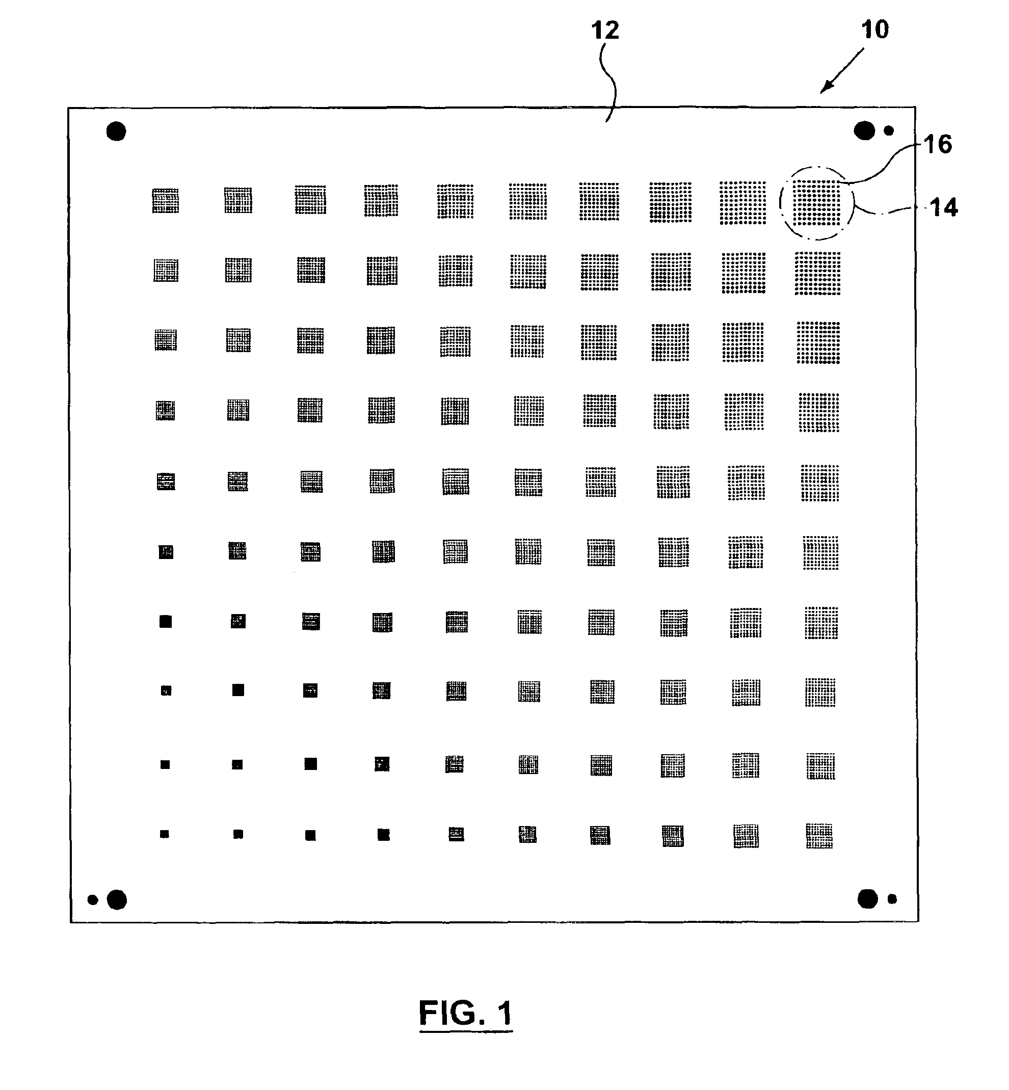
[0030]Referring first to FIG. 1, shown therein is a top view of an evaluation board 10 for surface mount technology in accordance with the present invention. Evaluation board 10 provides a substrate for a surface 12. On surface 12, there are a plurality of board pad patterns 14. Each board pad pattern 14 comprises a plurality of board pads 16 (only one board pattern and only one board pad is labeled for simplicity). Each board pad 16 is a conductive metallic material such as copper or gold which is provided on the surface 12 of the evaluation board 10 using circuit board manufacturing techniques that are well known to those skilled in the art. Each board pad 16 may have a rectangular, paralleliped, square, circular or other shape as illustrated in FIGS. 5a-5g. Alternatively, some of the board pads 16 on the evaluation board 10 may have a rectangular shape while others may have a square, paralleliped or circular shape. The shape can be chosen to correspond with the shape of the compo...


PUM

PropertyMeasurementUnit
sizeaaaaaaaaaa
sizeaaaaaaaaaa
sizeaaaaaaaaaa

Abstract

This invention provides an evaluation board for evaluating one or more aspects of a surface mount technology system. In one aspect, the evaluation board has a substrate with at least one surface. A plurality of board pad patterns, each including a plurality of board pads, is formed on the surface. The different board pad patterns may have different shaped, sized and spaced board pads, allowing the characteristics of a surface mount technology to be tested on some or all of the board pad patterns at the same time and under uniform conditions. In another aspect, the surface may have a plurality of area-filled board pads similarly allowing a surface mount technology to be tested on the various area-filled board pads.

Description

FIELD OF THE INVENTION[0001]The invention relates to an evaluation board that can be used to evaluate certain aspects of the surface mount technology process. More particularly, this invention relates to an evaluation board that can be used to evaluate solder paste, stencil and circuit board manufacturing, and the printing and reflow processes used in surface mount technology.BACKGROUND OF THE INVENTION[0002]Electronic devices are typically manufactured by mounting electronic components on a printed circuit board (PCB) using surface mount technology (SMT). The electronic components generally have leads, balls or conductive pads (i.e. component pads) that make electrical and mechanical contact with corresponding conductive pads (i.e. board pads) on a surface of a PCB. The process that is used for attaching the electronic components to the PCB includes the stages of solder paste deposition (i.e. printing) on the PCB through a stencil, component placement on the pasted PCB and reflow o...

Claims


Application Information

Patent Timeline
Patent Type & Authority Patents(United States)
IPC IPC(8): H05K1/11H05K1/02G01N13/02
CPCH05K1/0266H05K1/111G01N2013/0225H05K2201/09381H05K2203/162H05K2201/09781H05K2201/10204H05K2201/10719H05K2201/094Y02P70/50
Inventor CONNELL, DAVID JAMESCHRISTIAN, BEVERLY HOWARD
Owner MALIKIE INNOVATIONS LTD
Why Eureka
Try Eureka