Implantable microscale pressure sensor system for pressure monitoring and management

a micro-scale pressure sensor and pressure monitoring technology, applied in the field of implantable micro-scale pressure sensor systems for pressure monitoring and management, can solve the problems of many parts of the eye, many questions that are unanswered about the true effects of iop, and individual measurements may be separated, so as to achieve the effect of increasing fluid pressur

Inactive Publication Date: 2005-05-10
BOARD OF TRUSTEES OPERATING MICHIGAN STATE UNIV
View PDF4 Cites 154 Cited by
  • Summary
  • Abstract
  • Description
  • Claims
  • Application Information

AI Technical Summary

Benefits of technology

[0017]Therefore, it is an object of the present invention to provide an improved method and system for the detection of fluid pressure in general and in animals including humans, particularly in the eye, which provides the ability to have continuous monitoring.

Problems solved by technology

Also, a visit to a physician's office is generally required, thus individual measurements may be separated by long periods of time.
Permanent damage to many parts of the eye, including the optic nerve and retina, can result within hours of the onset if the pressures are high enough.
From a research standpoint, there are many questions that are unanswered about the true effects of IOP.

Method used


Image

  • Implantable microscale pressure sensor system for pressure monitoring and management
  • Implantable microscale pressure sensor system for pressure monitoring and management
  • Implantable microscale pressure sensor system for pressure monitoring and management

Examples


Embodiment Construction

[0067]All patents, patent applications, government publications, government regulations, and literature references cited in this specification are hereby incorporated herein by reference in their entirety. In case of conflict, the present description, including definitions, will control.

Implant Options

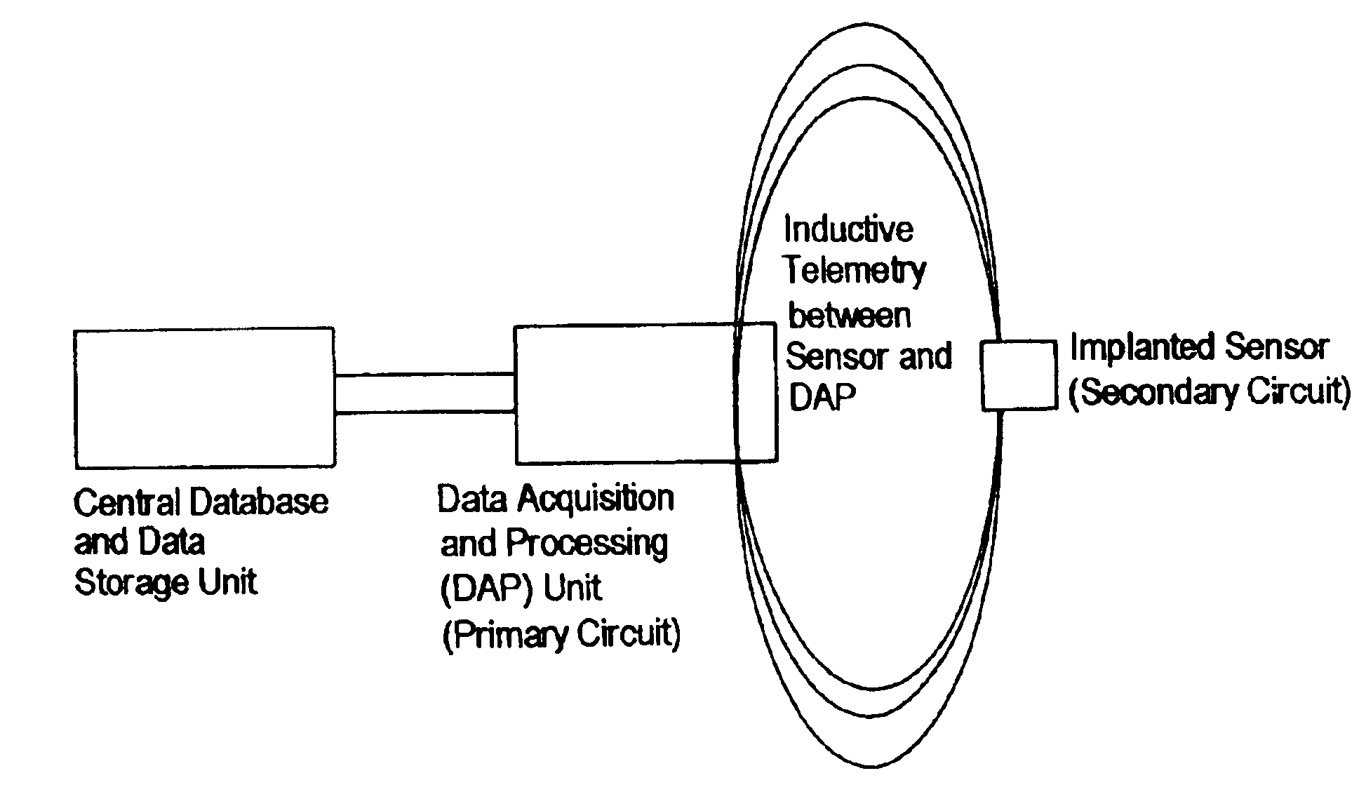
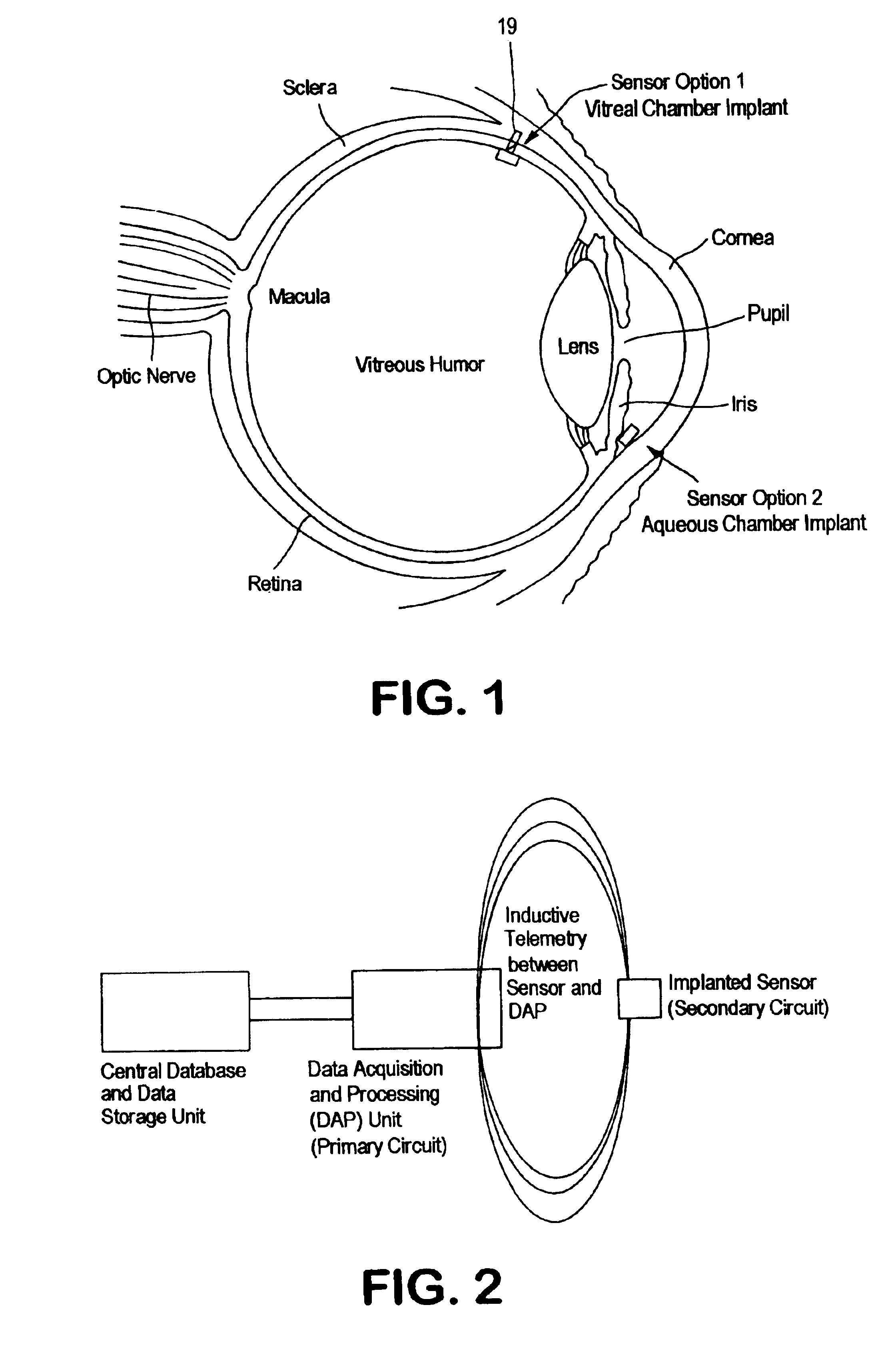
[0068]There are two options for the location of the sensor implant. The device will be located either in the vitreal chamber or the anterior chamber of the eye, shown in FIG. 1. The implant will be attached to the wall of the eye or attached to a tether so that the device can easily be located if there is a need for it to be removed.

Operating Range

[0069]Normal levels of IOP are considered to be around 16 mmHg. Pressures over 22 mmHg are considered to be moderately high while pressures greater than 45-50 mmHg can be extremely dangerous. The pressure sensor has been designed to measure pressures in the range of 0 to 60 mmHg. It should be noted that all parameters were designed with the i...


PUM


Abstract

A MEMS chip sensor (10, 20, 30, 40, 50, 60, 70) based upon detection of an induced inductance in the sensor is described. The sensor is used in an environment for detection of fluid pressures. The method and system is particularly used in animals, including humans, to sense pressure changes, particularly pressure in the eyeball.

Description

CROSS-REFERENCE TO RELATED APPLICATION[0001]This application claims priority to Provisional Patent Application No. 60 / 406,169 filed Aug. 27, 2002.STATEMENT REGARDING FEDERALLY SPONSORED RESEARCH OR DEVELOPMENT[0002]Not Applicable.Reference to a “Computer Listing Appendix submitted on a Compact Disc”[0003]Not Applicable.BACKGROUND OF THE INVENTION[0004]1. Field of the Invention[0005]The present invention relates to a method and system which uses a MEMS chip wireless capacitive sensor containing an inductance coil and spaced apart capacitive plates, one of which is in pressure contact with a fluid. The sensor can be used in general applications and in animals, including humans, to sense pressure, particularly in the eye. In particular, the sensor is in contact with the fluid in the vitreous chamber adjacent the cornea or in the aqueous chamber adjacent to the cornea of the eye. The sensor preferably includes an external antenna.[0006]2. Description of Related Art[0007]The problems in ...

Claims


Application Information

Patent Timeline
Patent Type & Authority Patents(United States)
IPC IPC(8): A61B3/16A61B5/00
CPCA61B5/0031A61B3/16
Inventor LLOYD, JOHN R.GROTJOHN, TIMOTHY A.WEBER, ARTHUR J.ROSENBAUM, FRANK R.GOODALL, GREGORY A.
Owner BOARD OF TRUSTEES OPERATING MICHIGAN STATE UNIV
Why Eureka
Try Eureka