Electrical heating device

Inactive Publication Date: 2005-05-10
HTTP HYPOTHERMIA THERAPY
View PDF25 Cites 26 Cited by
  • Summary
  • Abstract
  • Description
  • Claims
  • Application Information

AI Technical Summary

Benefits of technology

[0017]According to the present invention, all the above conditions are achieved by making the heating unit from two functionally different adjacent elements electrically insulated from each other (e.g., each covered by a thin insulating layer, e.g., lacquer, or a laminating layer such as PVC, polypropylene, etc.) each being made from a metal foil with a low specific resistivity of about 0.015-0.1 Ohm·mm2/m, such as aluminum, copper, iron, etc., the two elements having different resistance and different surface areas. That element, which is to be located closer to the body to be heated, has a relatively larger surface area and a relatively lower resistance as compared to the other element and serves as a distributor of heat created by the other element. In order to avoid local heating that could lead to burns, the surface of the heating unit through which heat is transferred to the body, i.e., the surface of the heat-distributor, should preferably be substantially equal to the surface area of the body parts to be heated. The operation of the heating unit thus provides for reducing the density of the heat flow that reaches the surface of the body to be heated

Problems solved by technology

These systems, however, give off heat to the environment and cause discomfort to the medical team.
Moreover, these systems suffer from the following drawbacks: the very high cost of warming units, occasional leaking as the result of cutting the unit, blocking of the system when a patient is too heavy, and the system being bulky and heavy (containing about 3.5-5 liters of water).
The warm air in the system escapes through the pores on the upper part of the blanket as well as through the flexible tubes into the theatre area, affecting the operating team and causing a certain degree of inconvenience.
Much body heat is lost within an hour of the start of anesthesia.
One of the problems of intraoperative warming is associated with the requirement for servo-controlled delive

Method used


Image

  • Electrical heating device
  • Electrical heating device
  • Electrical heating device

Examples


Example

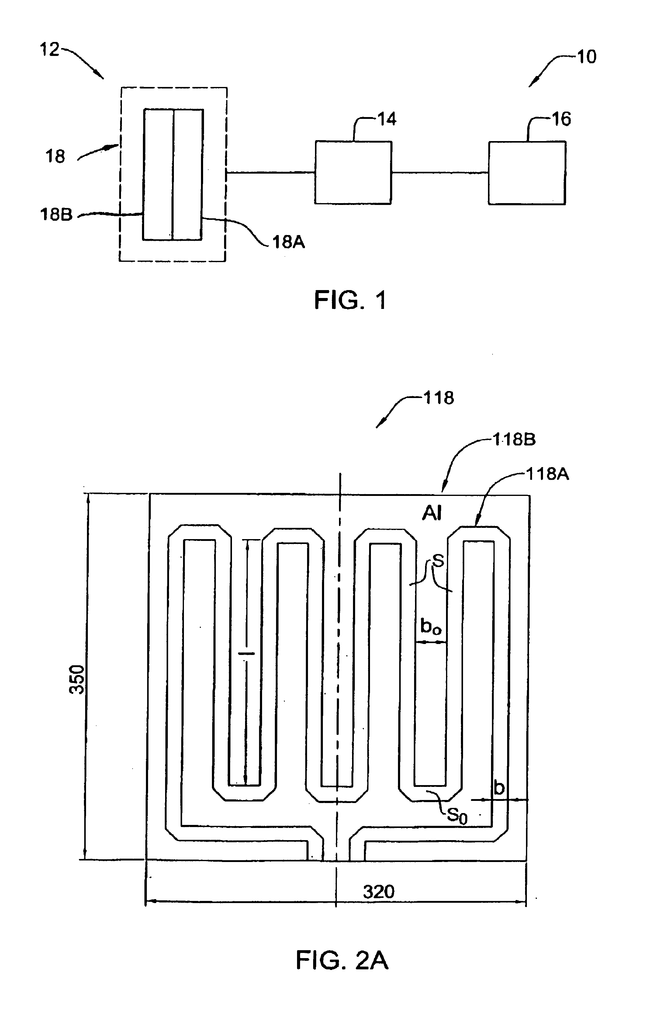
[0037]Referring to FIG. 1, there is illustrated a heating element 10 comprising a heating device 12 that includes a heating unit 18 according to the invention connectable to a power supply source 14; and a control unit 16. The construction of the control unit 16 does not form part of the present invention, and it may be of any known kind utilizing at least one temperature sensor, processors, contact and non-contact switches, etc. The power supply source 14 as a separate element is also known per se and therefore its construction and operation need not be specifically described, except to note that it operates to provide the normal operational mode of the heating unit 18 in accordance with instructions generated by the control unit 16.

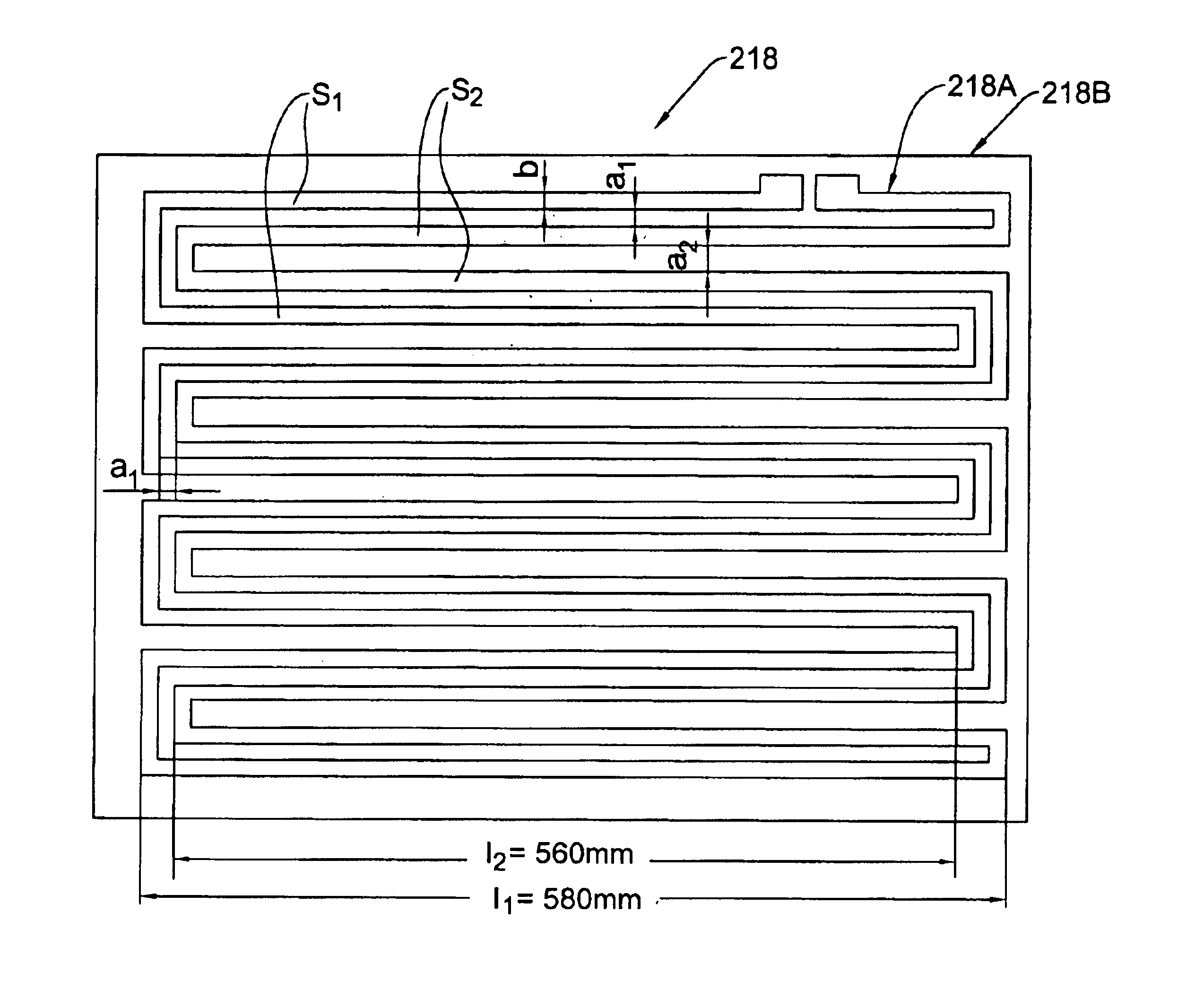
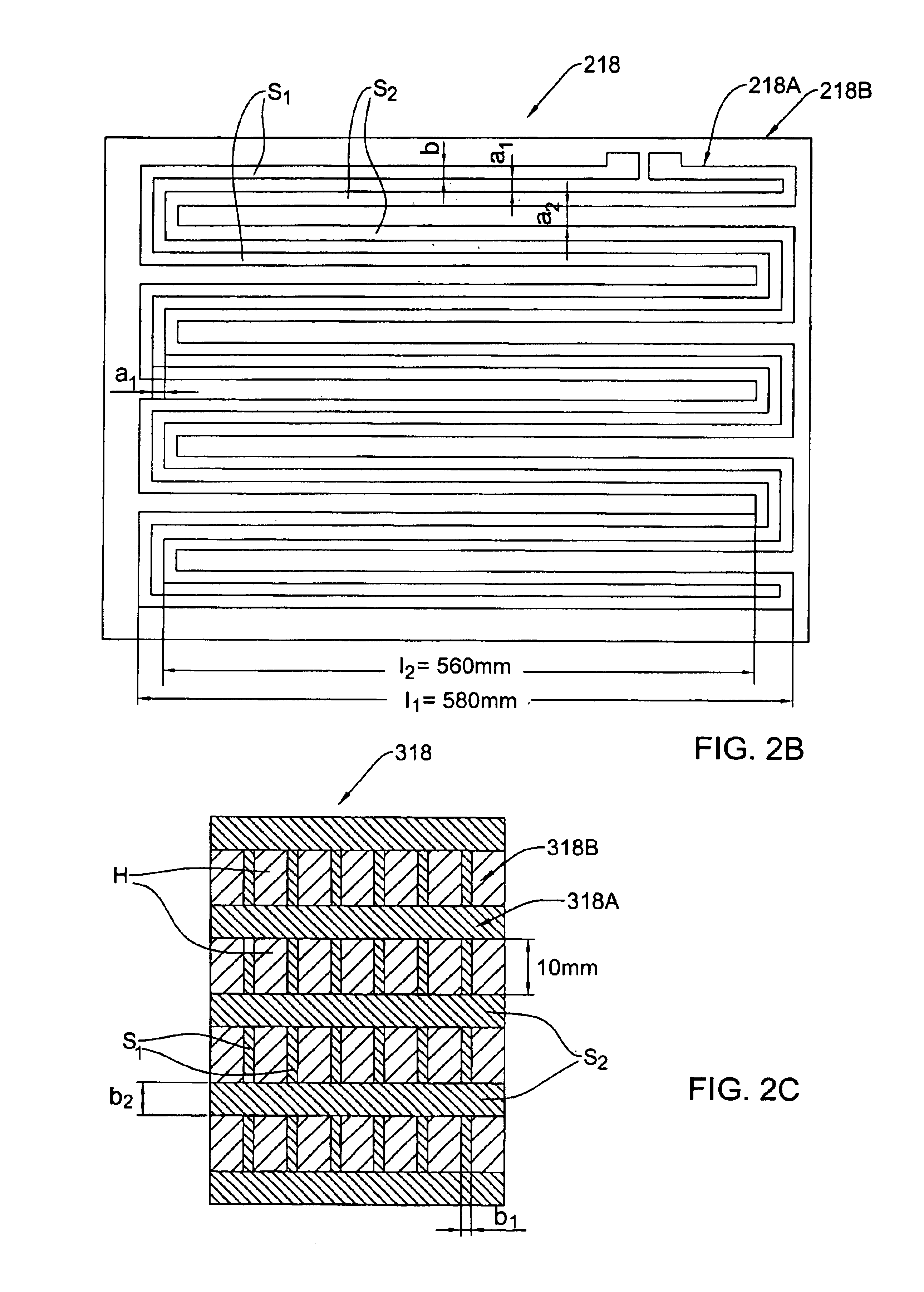
[0038]The heating unit 18 is composed of two adjacent elements 18A and 18B accommodated in spaced-apart planes for example at a 1 mm distance between the elements. The elements 18A and 18B are electrically insulated from each other, for example, by lami...


PUM


Abstract

A heating unit is presented for use in a heating device for surface heating of a body to enable maintaining a required temperature of the body. The heating unit is composed of first and second elements each made of a material with a specific resistivity in a range of about 0.01-0.01 Ohm·mm2/m, thereby enabling substantial flatness and flexibility of the heating unit. The first and second adjacent elements are accommodated in spaced-apart planes, are electrically insulated from each other, and have different resistance and different surface areas as compared to each other. The first element having the relatively high resistance and the relatively low surface area serves as a heater, and the second element, which is located closer to the body, when the heating unit is in the operation, serves as a distributor of heat created by the first element when connected to a power source. The heating unit is arranged such as to provide for compensating a magnetic field created by the heating unit when connected to the power source.

Description

FIELD OF THE INVENTION[0001]The present invention is generally in the field of heating techniques, and relates to an electrical heating unit and a heating device and system utilizing the same. The present invention is particularly useful for surface heating of a body, for example for heating a patient's body during surgical procedures and major operations.BACKGROUND OF THE INVENTION[0002]During a surgical procedure and within a certain time period thereafter, a patient's body requires to be externally heated. Heat transfer devices for transferring heat to the patient's body, which are used at present in operating rooms, are generally of two types: the first type utilizes a closed circuit with heated water circulating thereinside, and the second utilizes an open circuit, wherein heated air blows around the patient's body.[0003]The heating technique of the first kind involves covering a patient with a thin rubber cover with warm water circulating through the cover. A device, equipped ...

Claims


Application Information

Patent Timeline
IPC IPC(8): H05B3/34A61F7/02H05B3/26
CPCA61F7/007H05B3/342A61F2007/0001H05B2203/017H05B2203/004H05B2203/005H05B2203/014H05B2203/003
Inventor BIKOVSKY, DAVIDBAR-ADON, DORITH
Owner HTTP HYPOTHERMIA THERAPY
Why Eureka
Try Eureka