Apparatus for improving air quality

Inactive Publication Date: 2005-05-26
CLEAR SKIES UNLTD
View PDF6 Cites 11 Cited by
  • Summary
  • Abstract
  • Description
  • Claims
  • Application Information

AI Technical Summary

Benefits of technology

[0009] In accordance with the principles of the present invention an air quality improvement apparatus includes a reticulated foam having a ceramic substrate coated with catalytic material placed in the path of the air to be cleansed. Reticulated foam is a three-dimensional latticework of interconnected ligaments forming a porous, open-celled structure. Matter forming the structure covers only 5 to 10 percent of the overall volume. Thus, reticulated foam has an extremely large surface area per

Problems solved by technology

Thus, reticulated foam has an extre

Method used


Image

  • Apparatus for improving air quality
  • Apparatus for improving air quality
  • Apparatus for improving air quality

Examples


Embodiment Construction

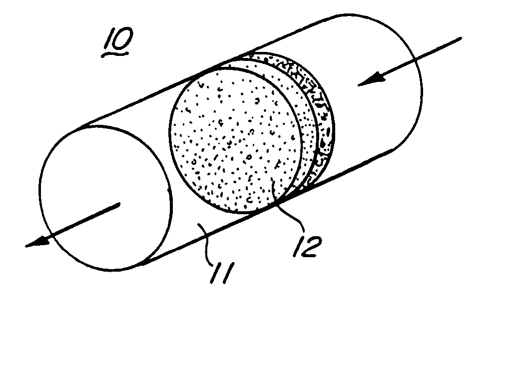
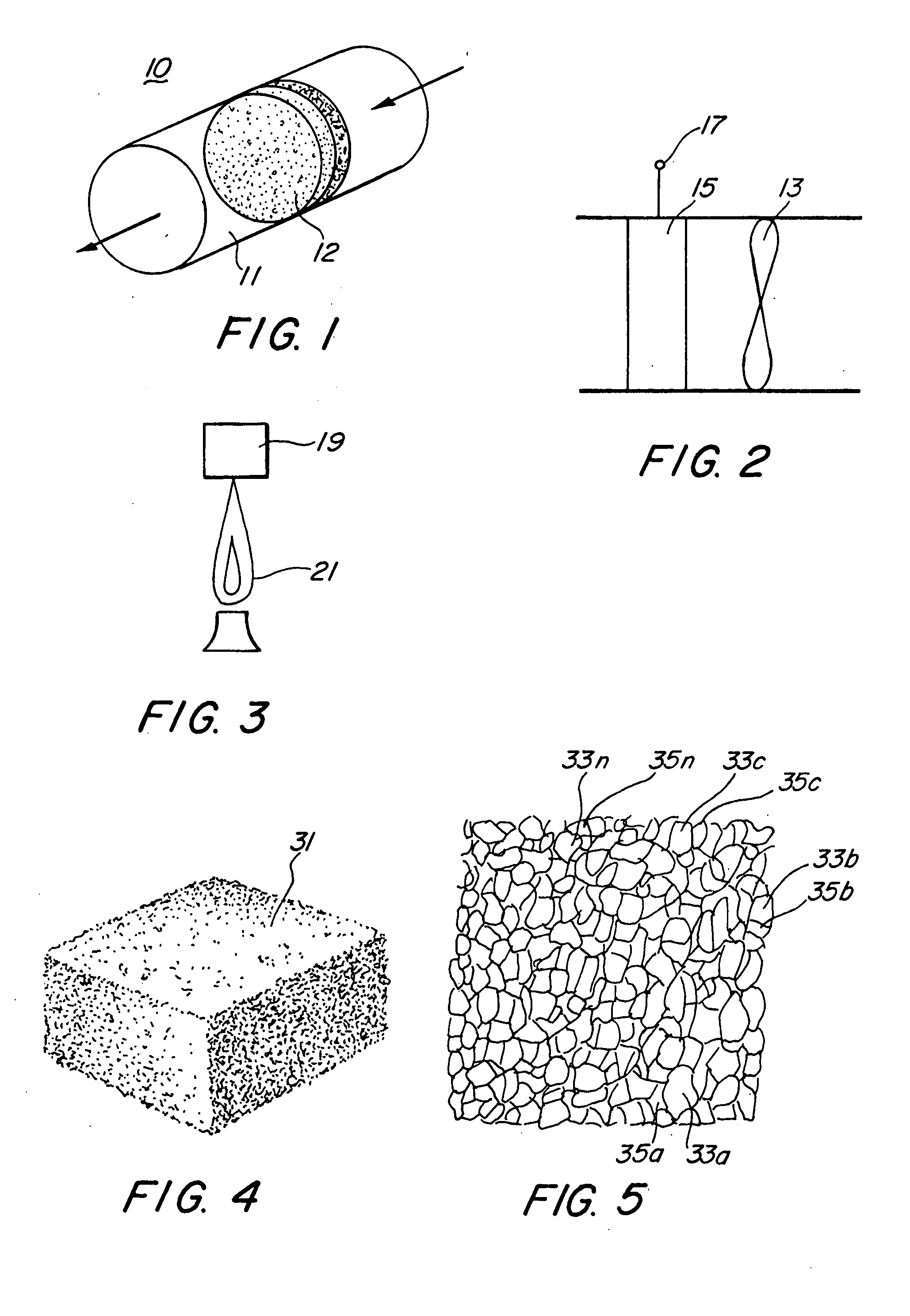
[0025] Refer-now to FIG. 1, wherein a schematic diagram of an apparatus 10 for reducing pollutants in air or other fluids is shown. Fluids from which pollutants are to be removed are lead to a guide 11 and directed through a catalytic converter 12, which converts pollutants in the fluid to harmless compounds, to emerge from the guide with pollutants in the fluid significantly reduced. A converter that may be employed in the guide is shown schematically in FIG. 2. A fan 13, for maintaining fluid flow, is positioned in the guide prior to a catalytic foam structure 15, which accomplishes pollutant reduction in the fluid. An energy source, not shown, may be coupled to the catalytic foam structure via a coupler 17 to maintain the catalytic foam structure at an efficient operating temperature.

[0026] Pollutants emitted from combustion processes may be reduced by positioning a catalytic converter 19 near the combustion source in the path of emissions or at the combustion source, as shown i...


PUM

PropertyMeasurementUnit
Flow rateaaaaaaaaaa
Densityaaaaaaaaaa
Volumeaaaaaaaaaa

Abstract

Pollutants in air or other fluids are converted to harmless compounds by positioning a catalyst coated reticulated foam in the path of the fluid flow. The reticulated foam is a three dimensional latticework of interconnected ligaments forming a porous, open-celled structure with a large internal surface area. Internal surfaces of the reticulated foam are coated with the catalyst. Catalytic conversion efficiency is maintained by fluid heat, an internal heating source, or external sources, such as combustion processes and radiation illumination.

Description

[0001] This application is a continuation-in-part of Ser. No. 09 / 368,837 filed Aug. 6, 1999 entitled WOODBURNING FIREPLACE EXHAUST CATALYTIC CLEANER.BACKGROUND OF THE INVENTION [0002] 1. Field of the Invention [0003] The invention pertains to the maintenance of air quality, and more particularly to the reduction of air pollutants contained in air, both indoor and outdoor. [0004] 2. Description of the Prior Art [0005] In recent years the quality of the air has received major consideration. Clean air has become more than a phrase. Significant efforts have been expended to minimize pollutants in the air we breathe. Some examples of these efforts are: emission standards have been imposed on automobile exhausts, incinerators in apartment houses have been shut down, and large garbage burning incinerators must meet established standards or be shut down. [0006] Though air pollution has traditionally been viewed as an outdoor problem, it has recently been shown that indoor pollution may be m...

Claims


Application Information

Patent Timeline
IPC IPC(8): F23G7/06F23G7/07F24B1/00
CPCF24B1/006F23G7/07Y02A50/20
Inventor SPARLING, RALPH C.GRACE, LANCE C.BUSSELLE, LINCOLN D.
Owner CLEAR SKIES UNLTD
Why Eureka
Try Eureka