
Carrier for golf bag

a golf bag and carrier technology, applied in the field of carriers, can solve the problems of reducing the room for the movement of the clubs, damage to each other, etc., and achieve the effects of reducing the effective diameter and interior volume of the bag, facilitating transportation, and reducing the room

Inactive Publication Date: 2005-05-17
WENZLER THOMAS
View PDF16 Cites 12 Cited by
  • Summary
  • Abstract
  • Description
  • Claims
  • Application Information

AI Technical Summary

Benefits of technology

[0014]A carrier for a golf bag completely encloses the golf bag and has a bottom section, a middle section and a top section. The bottom section is formed in part by a rigid plastic plate that supports two wheels. The wheels allow easy transportation of the carrier. The middle section of the bag supports pockets for carrying golf accessories such as shoes, balls and tees. The top section is padded and has at least one set of cords. Each cord is separated into two pieces. Each piece has an end secured to the interior of the bag and extends through a grommet to the exterior of the bag. The two cords can be pulled together and releasably connected. When the cords are pulled together and connected, the effective diameter and interior volume of the bag are reduced. This reduces the room for the clubs to move and cause damage to each other by impact.
[0015]The bag is provided with a top handle connected to the top of the bag, a bottom handle connected to the front of the bag proximate the bottom of the bag, a pair of hand straps connected to the middle section of the bag and a shoulder strap that traverses the length of the bag. These various handles and straps provide a variety of ways for the golfer to transport the bag. A zipper runs the full length of the bag to provide easy access to the interior of the bag. The carrier represents a convenient, easy-to-use manner to transport the bag by automobile or plane.

Problems solved by technology

This reduces the room for the clubs to move and cause damage to each other by impact.

Method used


Image

  • Carrier for golf bag
  • Carrier for golf bag
  • Carrier for golf bag

Examples


Embodiment Construction

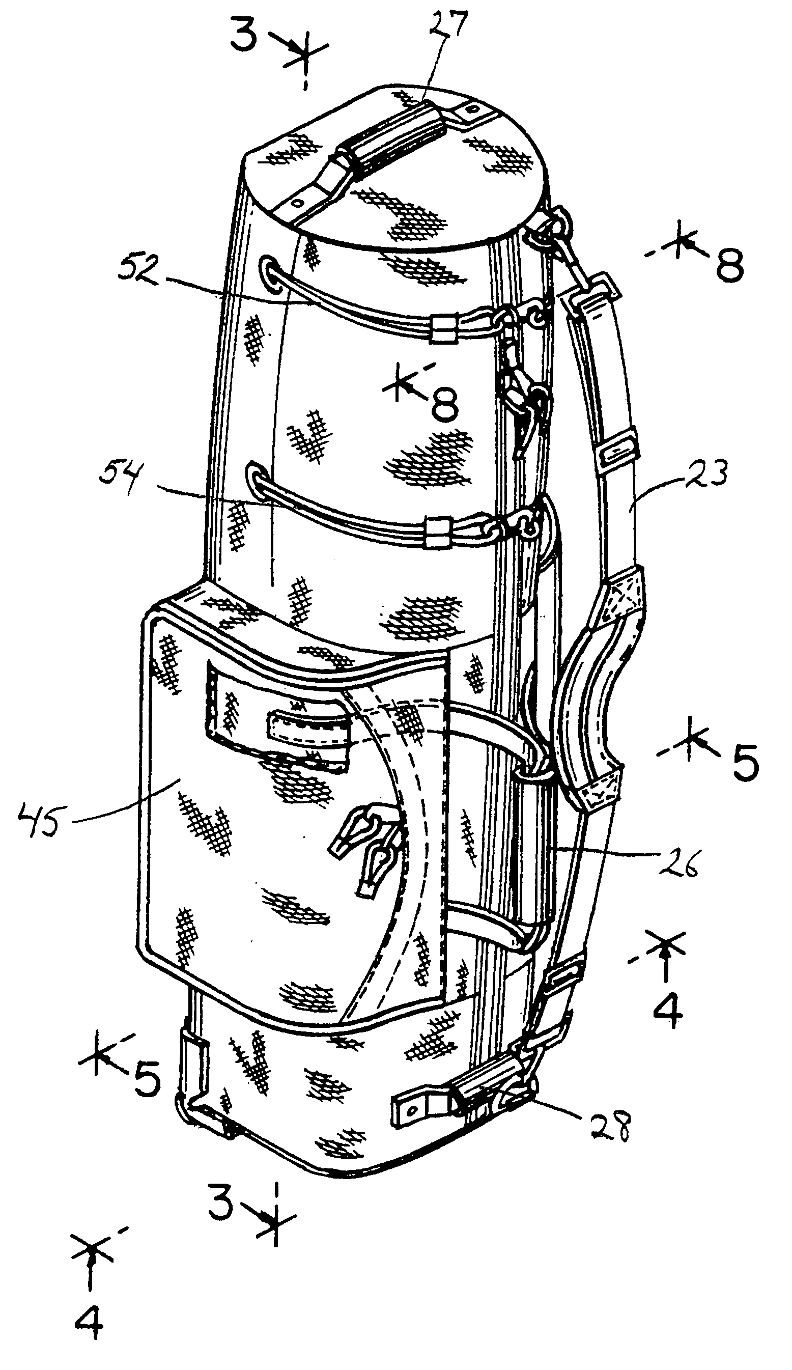
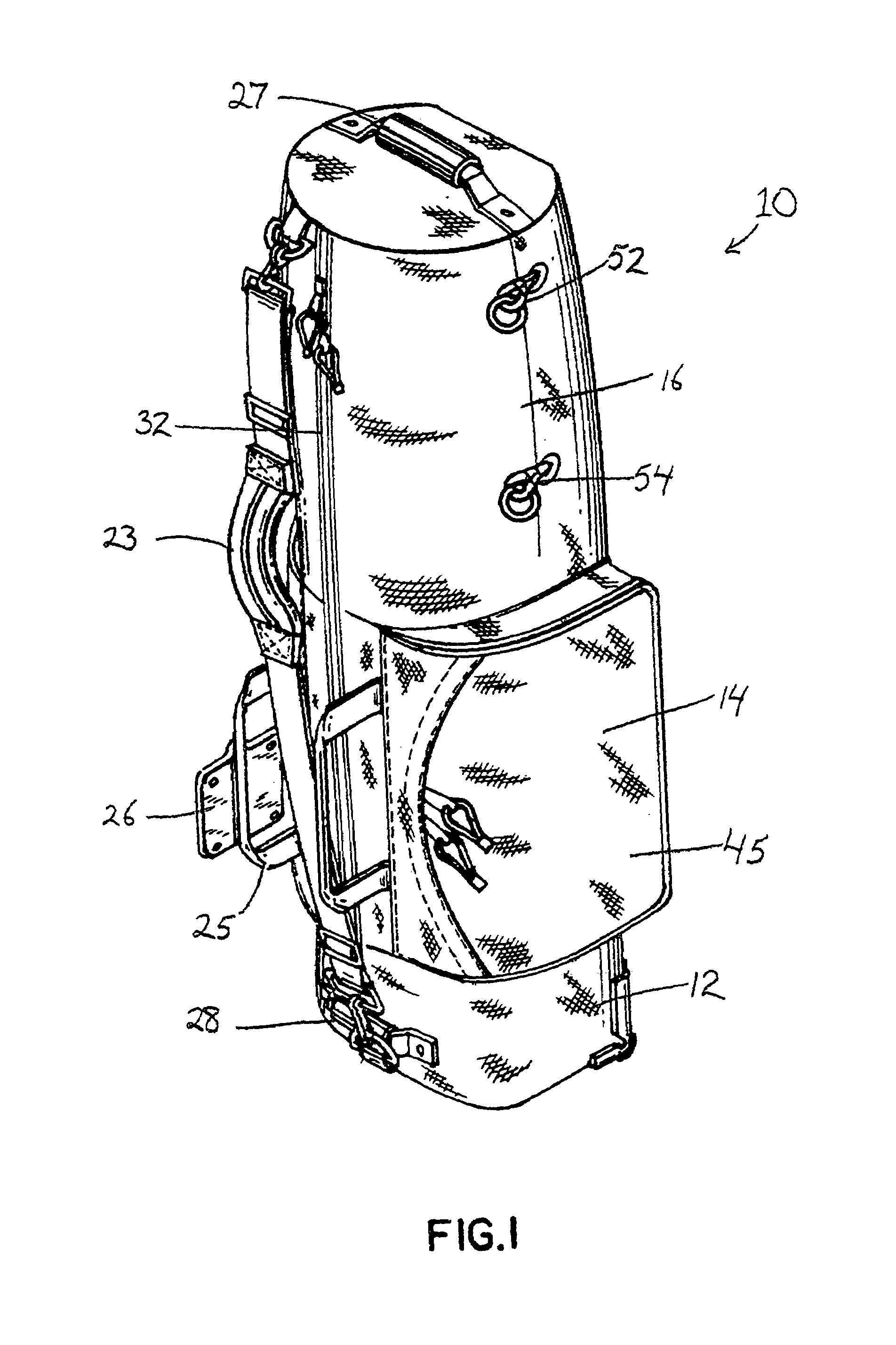
[0024]The general construction of the bag can be seen with reference to FIG. 1. The bag 10 is soft sided and has a bottom portion 12, a middle portion 14 and an upper portion 16. On the side of the bottom portion, proximate the bottom surface of the bag, a bottom handle 28 is provided. A pair of side pockets 45 extend from either side of the bag. These pockets are closed by zippers. The middle portion 14 also has a pair of hand straps 25. The hand straps are positioned on either side of the zipper 32 that traverses the full length of the bag. A strap connector 26 is permanently connected to one of the straps 25. A shoulder strap 32 is connected to D-rings located at the top and the bottom of the bag. A top handle 27 is connected to the top surface of the bag. A first cord 52 is seen as it extends through the grommet in the side of the bag. Located below this first cord is a second cord 54.

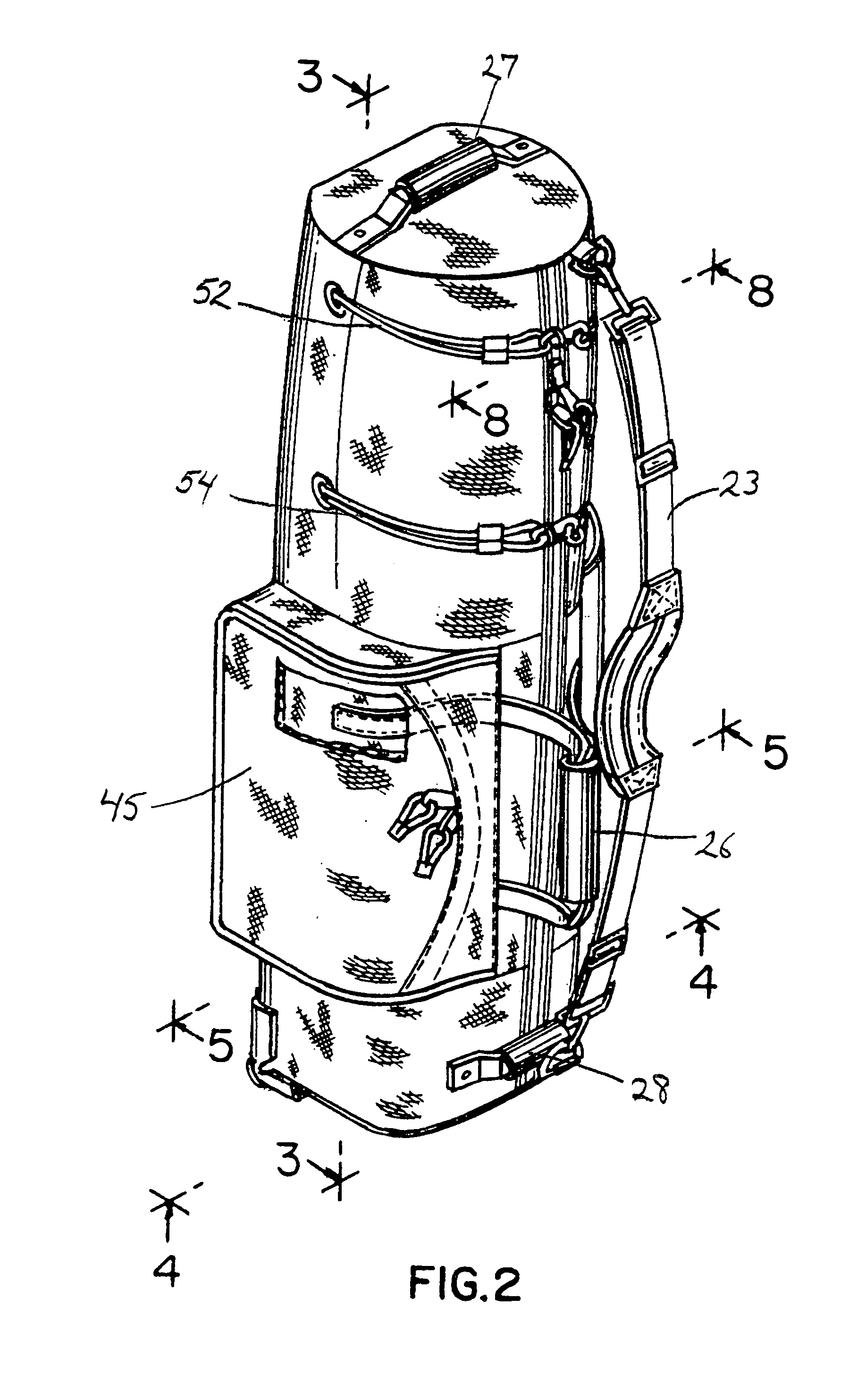
[0025]The left front perspective view is shown in FIG. 2. All of the elements are seen in this ...


PUM


Abstract

A carrier for a golf bag completely encloses the golf bag and has a bottom section, a middle section and a top section. The bottom section is formed in part by a rigid plastic plate that supports two wheels. The wheels allow easy transportation of the carrier. The middle section of the bag supports pockets for carrying golf accessories such as shoes, balls and tees. The top section is padded and has at least one set of cords. Each cord is separated into two pieces. Each piece has an end secured to the interior of the bag and extends through a grommet to the exterior of the bag. The two cords can be pulled together and releasably connected. When the cords are pulled together and connected, the effective diameter and interior volume of the bag are reduced. This reduces the room for the clubs to move and cause damage to each other by impact.

Description

CROSS-REFERENCE TO RELATED APPLICATION[0001]This application is a continuation of application Ser. No. 09 / 639,437, filed Aug. 12, 2000 now abandoned.FIELD OF THE INVENTION[0002]A carrier for the transportation and storage of a golf bag.BACKGROUND OF THE INVENTION[0003]Golf clubs have to be transported every time the golfer plays a round. The golfer most often keeps his golf clubs at home and must bring them to and from a golf course when playing. This necessitates placing the golf bag into the trunk and driving to the golf course. Also, it is common for golfers to take clubs on vacation in order to play at golf courses near their destination. Golf bags are large items and need to be checked at airports. When checked as baggage, the golf bag needs some way to retain the clubs within the bag. More importantly, the golf bag needs to be protected from damage as it is loaded through the baggage handling system on to and off of the plane.[0004]Many prior art devices have been developed fo...

Claims


Application Information

Patent Timeline
Patent Type & Authority Patents(United States)
IPC IPC(8): A63B57/00A63B55/00A63B55/60
CPCA63B55/08A63B55/005A63B55/60A63B55/406
Inventor WENZLER, THOMAS
Owner WENZLER THOMAS
Learn More