Flush mounted spider

a gripping device and spider technology, applied in the direction of rotary drilling, drilling pipes, well accessories, etc., can solve the problems of general economic impracticality of replacing the existing rotary table, and limited pipe size handling capacity of spiders, so as to reduce the rotational movement of the gripping apparatus

Inactive Publication Date: 2005-05-17
WEATHERFORD TECH HLDG LLC
View PDF32 Cites 95 Cited by
  • Summary
  • Abstract
  • Description
  • Claims
  • Application Information

AI Technical Summary

Benefits of technology

[0010]In one aspect, the bowl is formed as a recess in the inner wall of the housing. The hinges of the housing are progressively curved to accommodate the recess bowl, thereby increasing the tubular size handling capacity of the gripping apparatus.
[0012]In another aspect still, the apparatus may include includes a flange for mounting to a rotary table. In another embodiment, the flange may include one or more blocks for mating with a rotary table. The one or more blocks minimize the rotational movement of the gripping apparatus with respect to the rotary table.

Problems solved by technology

Because flush mounted spiders reside within the rotary table, the pipe size handling capacity of the spider is limited by the size of the rotary table.
Current spider designs further augment the problem of limited pipe size handling capacity.
However, the process of replacing the existing rotary table is generally economically impractical.
Another drawback of some spiders currently in use is the guide plate for facilitating the axial movement of the pipe string.
Further, many spiders have slips that are held in position in the bowl by friction.
As a result, only a limited amount of torque may be applied before slippage occurs between the slip and the bowl.

Method used


Image

  • Flush mounted spider
  • Flush mounted spider
  • Flush mounted spider

Examples


Embodiment Construction

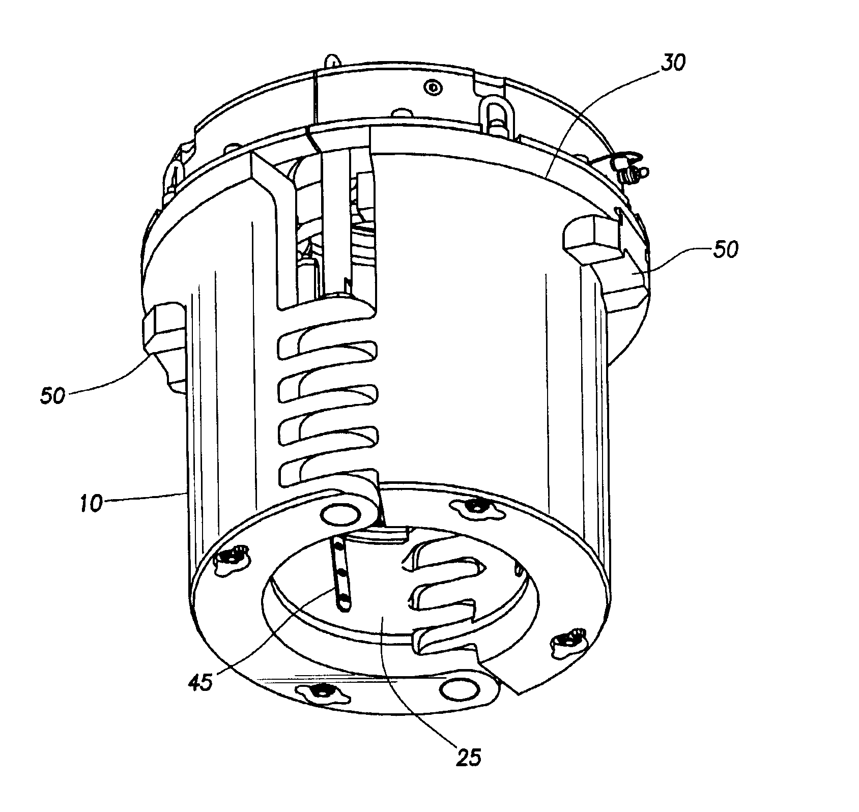
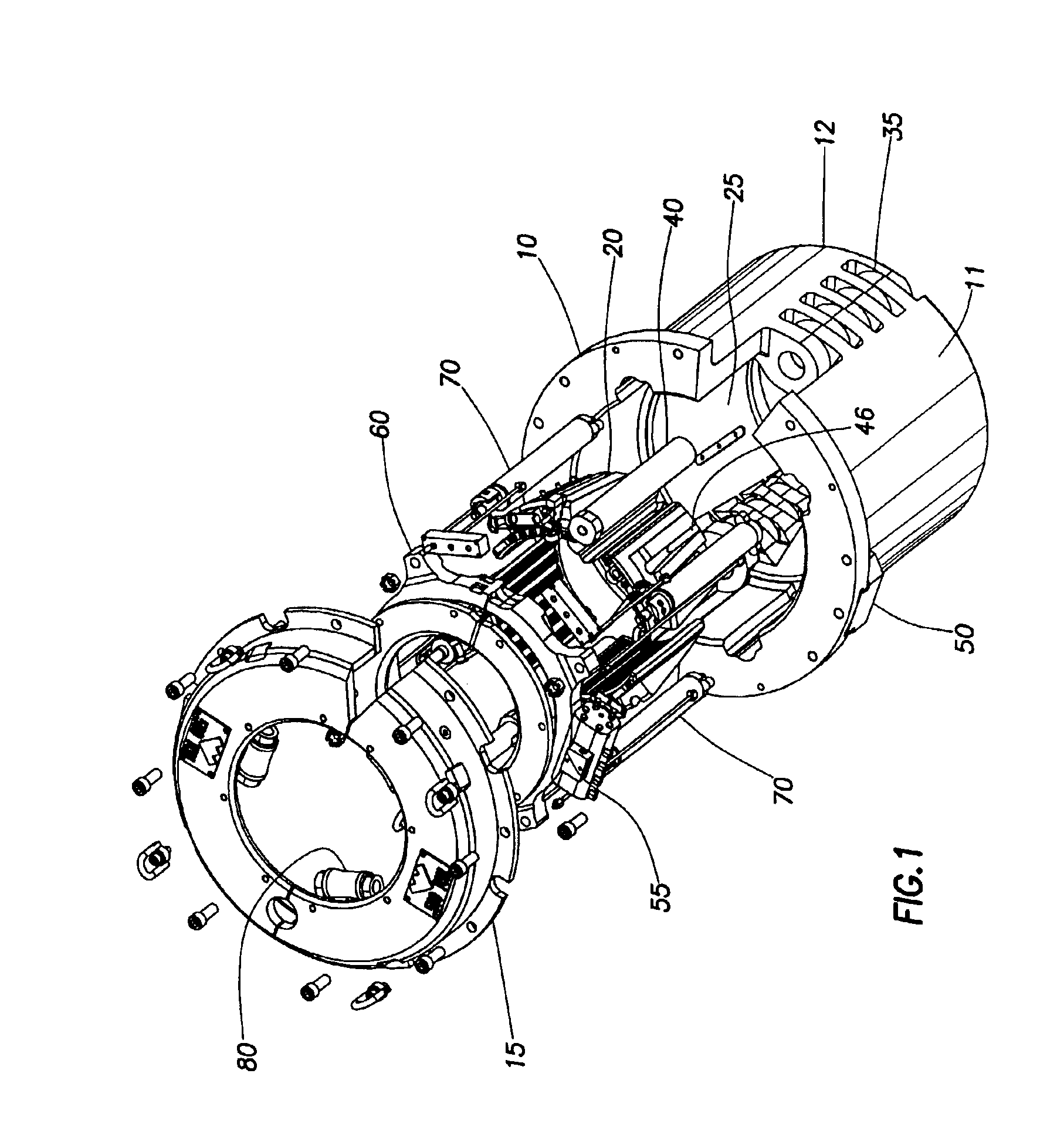
[0024]FIG. 1 shows an exemplary embodiment of a gripping apparatus 100 according to aspects of the present invention. As shown, the gripping apparatus 100 is a flush mounted spider 100 disposable within a rotary table (not shown). The spider 100 includes a body 10 for housing one or more gripping members 20 and a cover assembly 15 for the body 10.

[0025]The body 10 of the spider 100 is formed by pivotally coupling two body sections 11, 12 using one or more connectors 35. Preferably, hinges 35 formed on both sides of each body section 11, 12 are used to couple the two body sections 11, 12. Alternatively, the body sections 11, 12 may be hinged on one side and selectively locked together on the other side. A bowl 25 extends vertically through a lower portion of the body 10 to house gripping members 20 such as a slip assembly 20 as shown in FIG. 2.

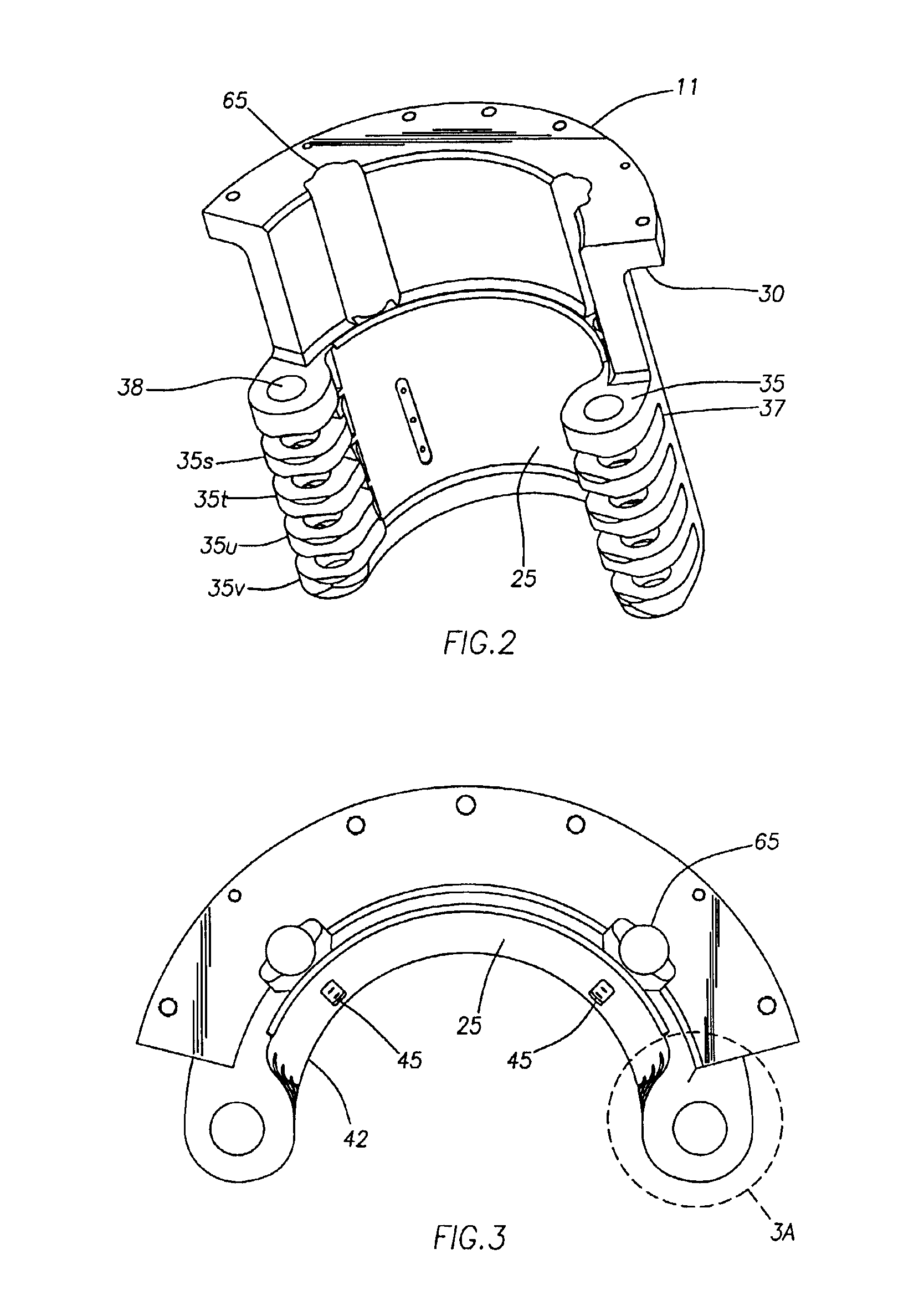
[0026]FIG. 2 shows one 11 of the body sections 11, 12 forming the spider body 10. A flange 30 is formed on an upper portion of the body sectio...


PUM


Abstract

A gripping apparatus for supporting a tubular includes a longitudinal opening extending therethrough. A bowl is formed on an inner wall of the housing to provide an incline surface for one or more gripping members. As the gripping members are move down along the incline, the incline causes the gripping members to move radially toward the tubular and contact the tubular. In one embodiment, the housing comprises two body portions coupled together using one or mores hinges. In one aspect, the bowl is formed as a recess in the inner wall of the housing. The hinges of the housing are progressively curved to accommodate the recess bowl, thereby increasing the tubular size handling capacity of the gripping apparatus. In another embodiment, the apparatus may include guide keys that mate with guide slots formed on an outer surface of the gripping members to minimize the rotational movement of the gripping members relative to the housing. In another embodiment, the apparatus may include a leveling ring connected to the one or more gripping members for synchronizing the movement of the one or more gripping members. In another embodiment still, the flange may include one or more blocks for mating with a rotary table. In another embodiment still, the apparatus may include one or more adjustable guide rollers to facilitate movement of the tubular within the housing.

Description

BACKGROUND OF THE INVENTION[0001]1. Field of the Invention[0002]Embodiments of the present invention generally relate to a gripping apparatus for supporting tubulars. Particularly, the aspects of the present invention relate to slip type gripping assembly disposable within a rotary table.[0003]2. Description of the Related Art[0004]The handling of pipe strings has traditionally been performed with the aid of a spider. Typically, spiders include a plurality of slips circumferentially surrounding the exterior of the pipe string. The slips are housed in what is commonly referred to as a “bowl”. The bowl is regarded to be the surfaces on the inner bore of the spider. The inner sides of the slips usually carry teeth formed on hard metal dies for engaging the pipe string. The exterior surface of the slips and the interior surface of the bowl have opposing engaging surfaces which are inclined and downwardly converging. The inclined surfaces allow the slip to move vertically and radially re...

Claims


Application Information

Patent Timeline
Patent Type & Authority Patents(United States)
IPC IPC(8): E21B19/10E21B19/00E21B19/24
CPCE21B3/04E21B19/24E21B19/10E21B19/102
Inventor SHAHIN, DAVIDHEIDECKE, KARSTEN
Owner WEATHERFORD TECH HLDG LLC
Why Eureka
Try Eureka