Panel light source device and back light module for liquid crystal display device

Inactive Publication Date: 2005-05-17
HANNSTAR DISPLAY CORPORATION
View PDF12 Cites 15 Cited by
  • Summary
  • Abstract
  • Description
  • Claims
  • Application Information

AI Technical Summary

Benefits of technology

[0019]Accordingly, the back light module or the panel light source according to the present invention includes a reflecting type polarizer and thus provides the polarized light without lowering the energy efficiency. Also, the polarized light may transmit through the polarizing film of the liquid crystal display to minimize the

Problems solved by technology

Also, the TFT (Thin Film Transistor) switching elements of the liquid crystal panel 10 may be damaged by the heat of the back light source.
Because of these required structural elements, it is very difficult to reduce the thickness of the direct type back light module 21.
Further, the cost of the liquid crystal display will increase more and mo

Method used


Image

  • Panel light source device and back light module for liquid crystal display device
  • Panel light source device and back light module for liquid crystal display device
  • Panel light source device and back light module for liquid crystal display device

Examples


Example

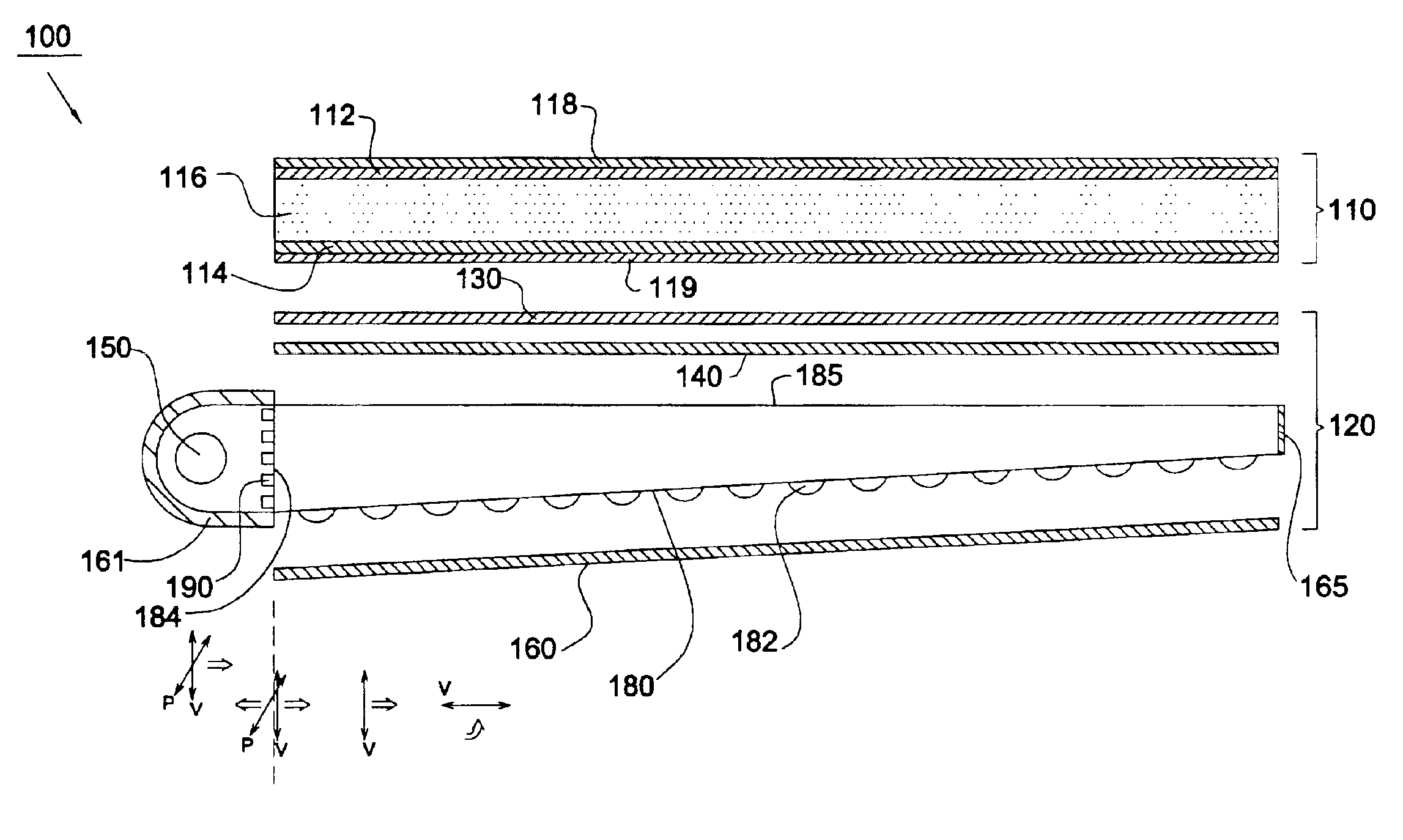
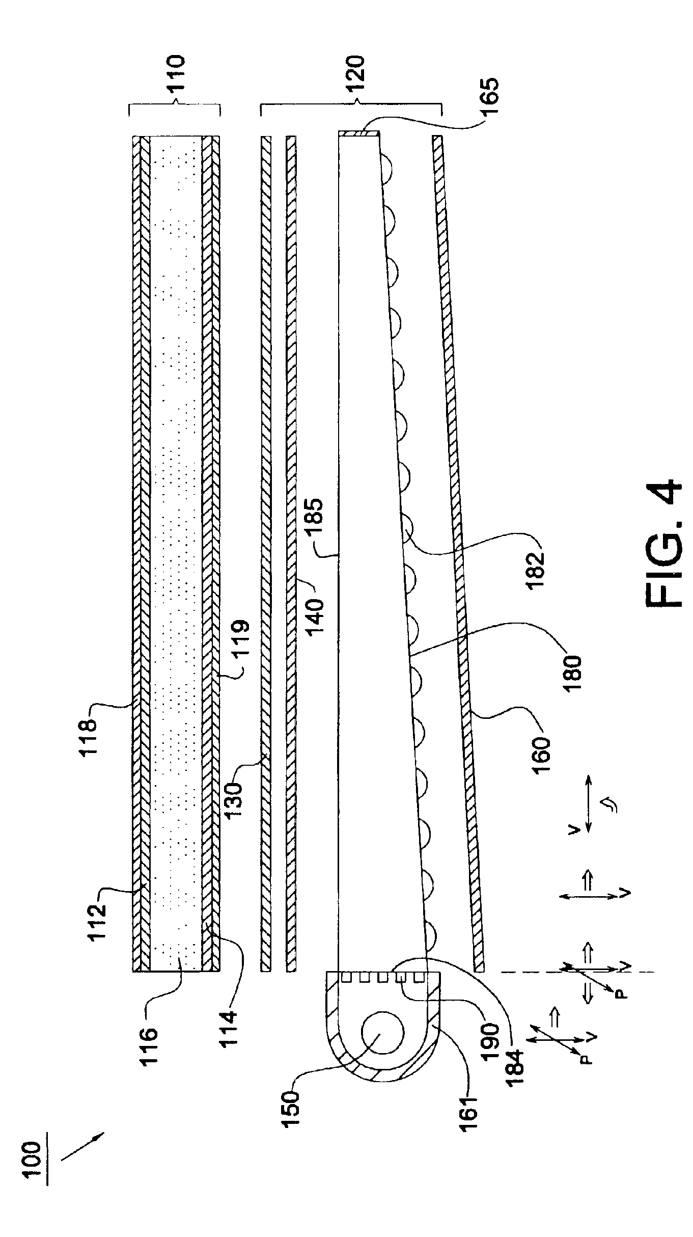
[0029]Referring to FIG. 4, it depicts a liquid crystal display 100 according to a first embodiment of the present invention. The liquid crystal display 100 includes a liquid crystal panel 110 and a back light module 120. The liquid crystal panel 110 has two transparent substrates 112, 114 and a liquid crystal material 116 disposed therebetween. The outer surfaces of transparent substrates 112, 114 of the liquid crystal panel 110 are covered with polarizing sheet 118, 119, and the inner surfaces thereof are provided with switching elements for changing the alignments of the molecular of the liquid crystal material 116 and thus generating images.

[0030]The back light module 120 is served as a panel light device for illuminating the liquid crystal panel 110. The back light module 120 includes a light source 150, a U-shaped reflector 161 surrounding the light source 150, a wedge light guide 180 and a plurality of layers of optical films, such as diffusing sheet 140 and a prism sheet 130....


PUM


Abstract

A panel light source device comprises a light source, a U-shaped reflector surrounding the light source, a light guide, and a plurality of metal grid wires. The light guide has an incoming surface facing the light source and an outgoing surface. The light is transmitted into the light guide from the incoming surface and then transmitted out of the light guide from the outgoing surface. The metal grid wires are disposed between the incoming surface and the light source for transmitting the light with a predetermined polarization therethrough and reflecting the rest light therefrom.

Description

CROSS REFERENCE TO RELATED APPLICATION[0001]This application claims the priority benefit of Taiwan application serial no. 091117235, filed Jul. 26, 2002, the full disclosure of which is incorporated herein by reference.BACKGROUND OF THE INVENTION[0002]1. Field of the Invention[0003]The present invention generally relates to a panel light device, and more particularly, to a back light module for a liquid crystal display (LCD).[0004]2. Description of the Related Art[0005]Referring to FIG. 1, it depicts the structure of a conventional liquid crystal display. Generally, the liquid crystal display device includes a liquid crystal panel 10 which has two substrates and a liquid crystal material sealed therebetween, a back light unit 20 disposed under the liquid crystal panel 10, and cases 11 and 12.[0006]The back light unit 20 is utilized to distribute the light from a light source uniformly over the surface of the liquid crystal panel 10. There are several kinds of back light units 20 suc...

Claims


Application Information

Patent Timeline
IPC IPC(8): F21V8/00G02F1/1335G02F1/13G02B6/00G02F1/13357
CPCG02F1/13362G02B6/0016G02B6/0038G02B6/005G02B6/0068G02B6/0071G02B6/0055
Inventor YANG, KEI HSIUNG
Owner HANNSTAR DISPLAY CORPORATION
Why Eureka
Try Eureka