
Method of forming a one piece hockey stick

a one-piece, hockey stick technology, applied in the field of one-piece hockey stick formation, can solve the problems of adverse effects of sanding and painting the joint, adverse effects of mechanical joints on the flex and mechanical integrity of prior art hockey sticks, and inability to mitigate these adverse effects

Inactive Publication Date: 2005-05-17
TRUE TEMPER SPORTS
View PDF20 Cites 24 Cited by
  • Summary
  • Abstract
  • Description
  • Claims
  • Application Information

AI Technical Summary

Problems solved by technology

Unfortunately, the added weight of the joint; the mechanical play inherent in the joint, and the inherent yield of the bonding material adversely affect the play of the stick.
Merely sanding and painting the joint cannot mitigate these adverse effects.
Regardless of the type of mechanical joint employed, any mechanical joint adversely affects the flex and mechanical integrity of the prior art hockey sticks.
Because the added weight of the reinforced joint lies near the end of the stick, the stick suffers from a disproportionately large increase in moment of inertia, thereby slowing the player's downswing considerably.
Worse yet, the designer, in seeking to optimize shaft flexure, must contend with an inflexible portion of the shaft, the joint, which impedes the optimization of the stick.
Poor mechanical joints at the blade / shaft transition allow greater blade rotation.
Likewise, poor mechanical joints allow translational movement between the blade and the shaft.
While such relative motion may be small, the distance the hockey puck travels amplifies the poor aim caused by such relative movement.
Moreover bonding does little to eliminate these problems because the adhesive employed can yield.
These shortcomings make repeatable shots difficult with a given stick.
They also make performance differences between sticks unpredictable.

Method used


Image

  • Method of forming a one piece hockey stick
  • Method of forming a one piece hockey stick
  • Method of forming a one piece hockey stick

Examples


Embodiment Construction

[0019]The following description of the preferred embodiments is merely exemplary in nature and is in no way intended to limit the invention, its application, or uses.

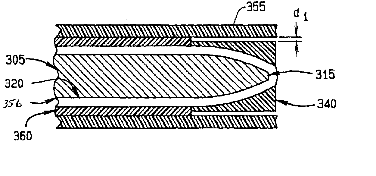
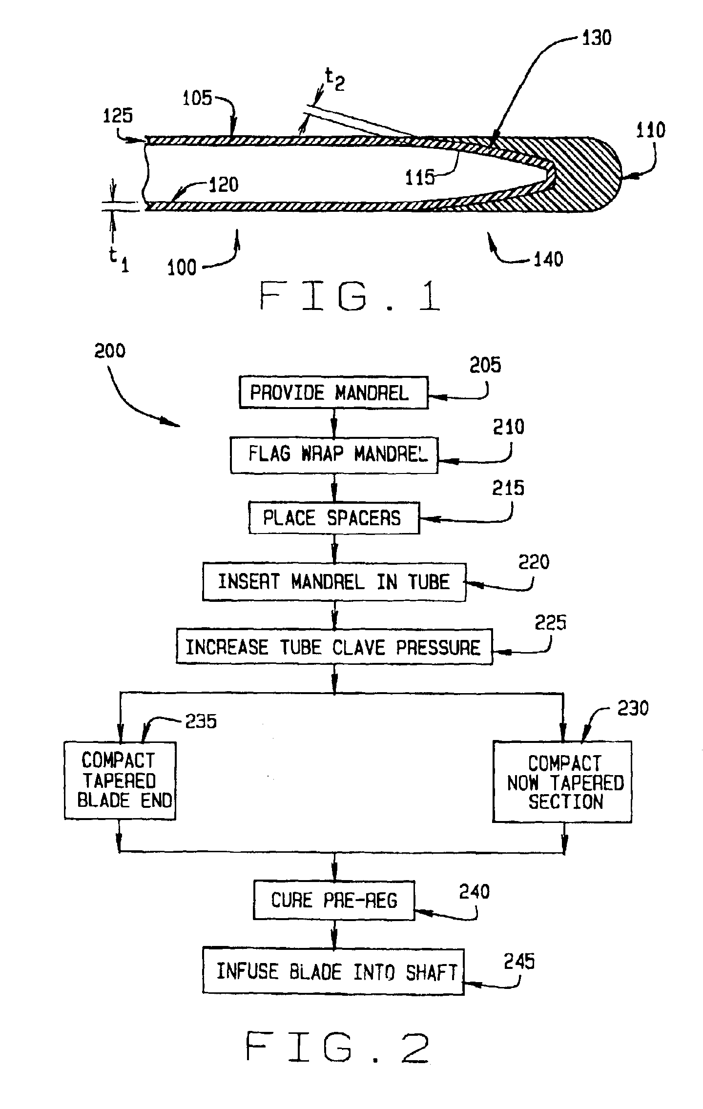
[0020]With reference to FIG. 1 a hockey stick 100 per the present invention is shown. The stick has a shaft 105 and a blade 110 (shown extending vertically from the page). The shaft 105 has a tapered blade end 115 where the shaft 105 to blade 110 transition 140 occurs. The shaft also has a non tapered section 120 generally extending to a grip end (not shown) for handling the stick 100. A carbon and Kevlar composite may be used, for example, to form a thin wall 125 of the shaft 105.

[0021]More particularly, the thin wall 125 has a tapered blade end and a non tapered section coincident with those of the shaft 105. Both the non tapered section 120 and the tapered blade end 115 have been compacted during manufacture. The amount by which the non tapered section 120 and the tapered blade end 115 are compacted may differ. Accor...


PUM

PropertyMeasurementUnit
Pressureaaaaaaaaaa
Diameteraaaaaaaaaa

Abstract

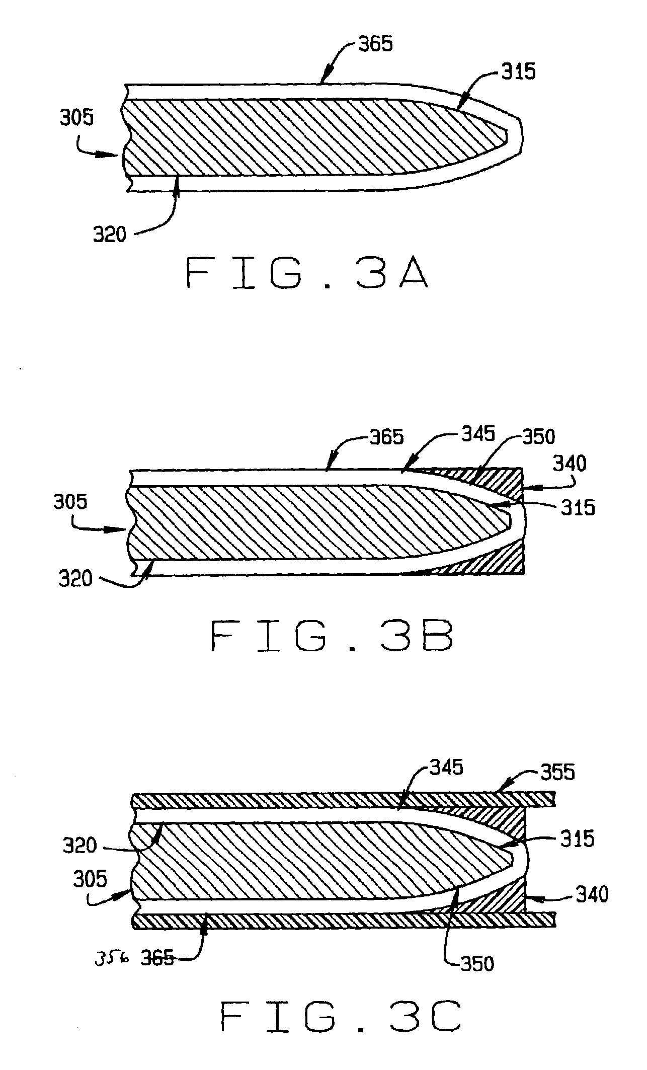
A method of manufacturing a one piece, composite, hockey stick in an autoclave. A mandrel is provided which has a non uniform cross section. Pre-preg flags are wrapped around the mandrel. Provision is made so that when the wrapped mandrel is inserted in a pressure application tube, a portion of the wrapped mandrel is separated from the pressure application tube by one or more spacers. Pressure is then applied to the pressure application tube which in turn applies the pressure to the spacers. The spacers then apply the pressure to the wrapped mandrel to compact the pre-preg on the wrapped mandrel. Next the spacers are removed and the pre-preg is cured. Finally, a blade is formed around the pre-preg flag.

Description

FIELD OF THE INVENTION[0001]The present invention relates to a method of forming a one piece hockey stick, and more particularly to forming the shaft for a one piece, composite, hockey stick with superior playing characteristics.BACKGROUND OF THE INVENTION[0002]Slap shots can propel hockey pucks at over 100 mph. During the downswing of a slap shot, the shaft of the golf club flexes thereby storing mechanical energy via the strain of the shaft. When the stick impacts the puck, the strain energy relieves and transfers to the puck via the blade of the stick. Simultaneously, the player is following through by forcefully pushing, with the weight of his body, the stick against the puck. Thus, the combination of force from the follow through, momentum exchange from the impact, and sudden energy release from the shaft propels the puck at much greater velocity than a mere momentum exchange with the blade would, frequently in excess of 100 mph.[0003]Many prior art hockey sticks employ a blade...

Claims


Application Information

Patent Timeline
IPC IPC(8): B29C70/04B29C70/44
CPCB29C70/446B29L2031/5227
Inventor HAAS, NEALMOLLNER, BRIAN
Owner TRUE TEMPER SPORTS
Learn More