Display monitor for multi-optical-path photoelectric safety apparatus and multi-optical-path photoelectric safety apparatus including a display monitor

Inactive Publication Date: 2005-05-17
KEYENCE
View PDF8 Cites 39 Cited by
  • Summary
  • Abstract
  • Description
  • Claims
  • Application Information

AI Technical Summary

Benefits of technology

[0014]It is therefore an object of the invention to provide a display monitor for a multi-optical-path photoelectric safety apparatus for enabling the user to easily check the light incidence/light blo

Problems solved by technology

According to the display method in the related art, an overview of the number of blocked optical paths and the locations thereof can be generally known, but the information to identify the locations is not displayed and thus it is hard for the user to identify them.
For example, when a special function such as a blanking function is set for a specific optical path by teaching the apparatus this function, it is difficult to determine whether or not the function is correctly set for the intended optical path on the display secti

Method used


Image

  • Display monitor for multi-optical-path photoelectric safety apparatus and multi-optical-path photoelectric safety apparatus including a display monitor
  • Display monitor for multi-optical-path photoelectric safety apparatus and multi-optical-path photoelectric safety apparatus including a display monitor
  • Display monitor for multi-optical-path photoelectric safety apparatus and multi-optical-path photoelectric safety apparatus including a display monitor

Examples


Example

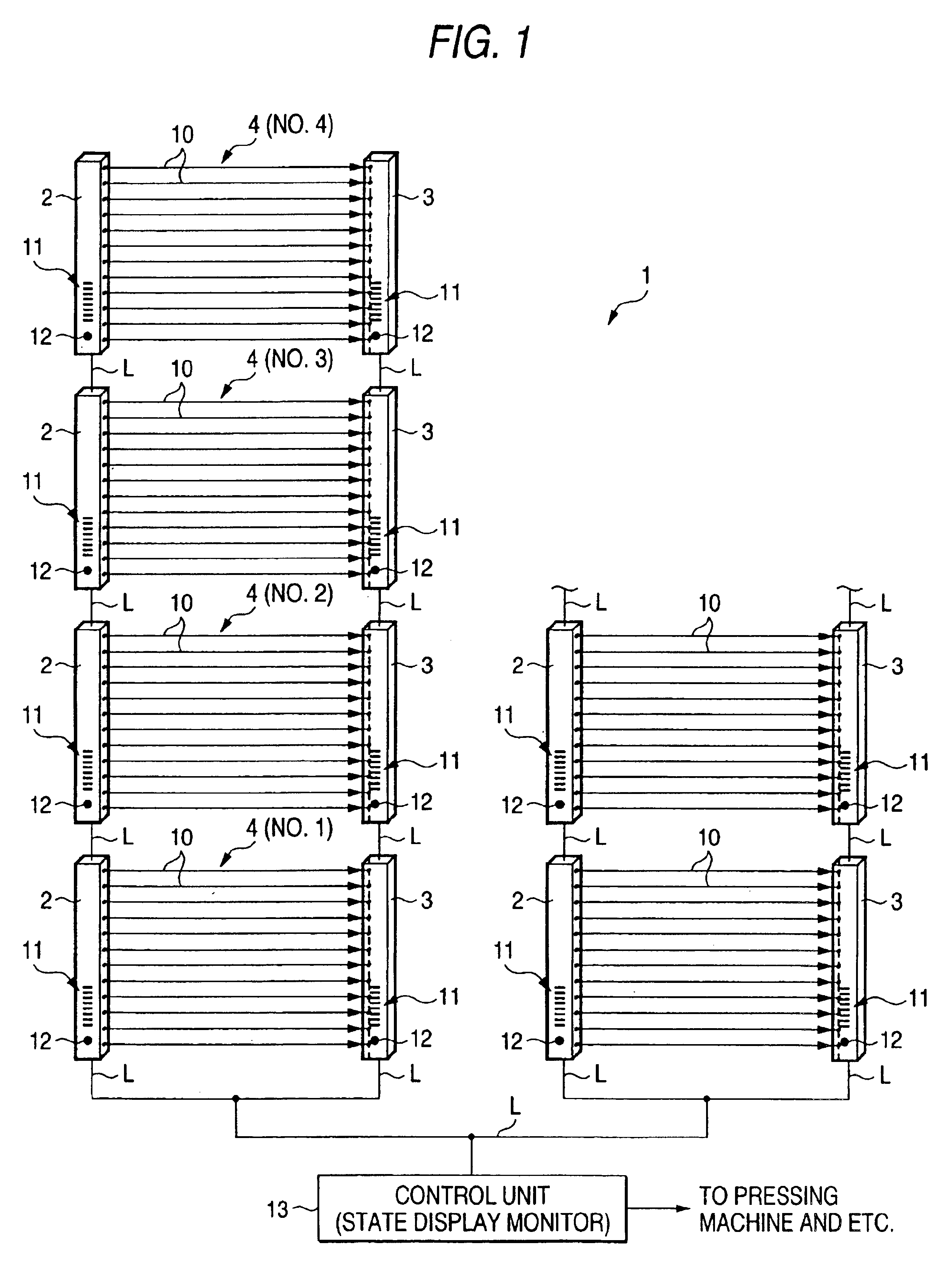
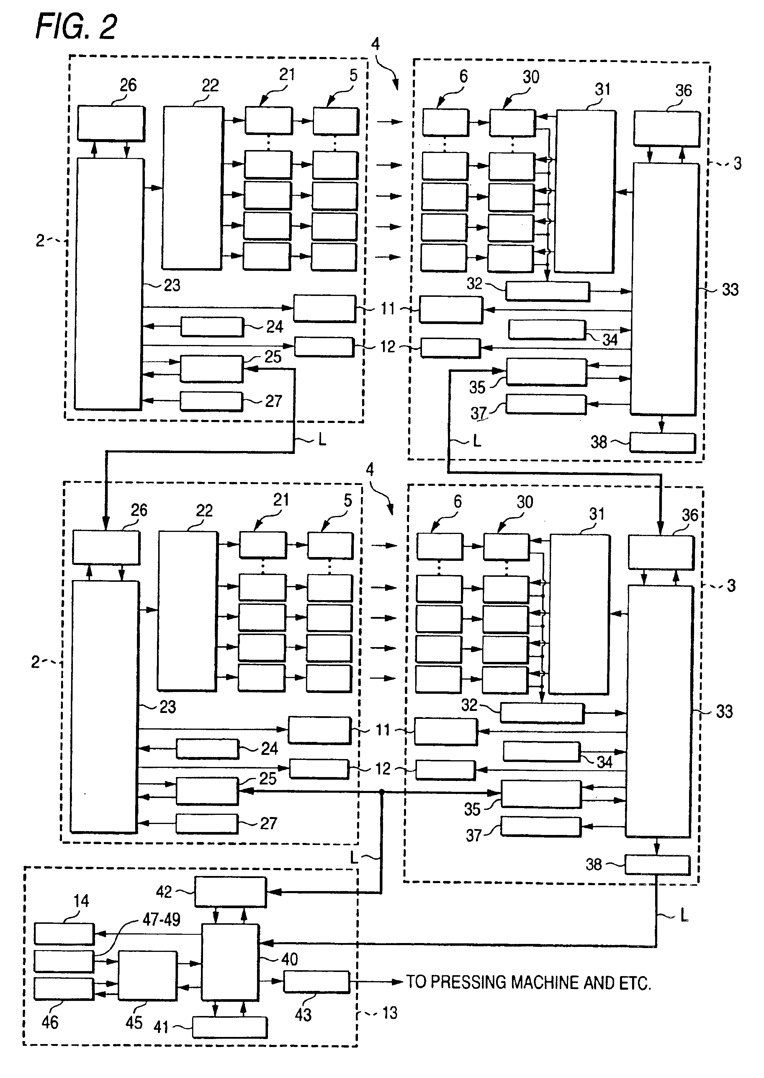
[0034]Referring to FIG. 1, a multi-optical-path photoelectric safety apparatus 10 of a first embodiment includes a multi-optical-path photoelectric sensor unit 4 comprising a light emitter 2 and a light receiver 3. Additional units 4 can be installed in series or in parallel via communication lines or signal lines L.

[0035]The light emitter 2 has an elongated case in which N light emission elements 5 (FIGS. 2 and 3) are equally spaced from each other in a row along the lengthwise direction of the case. The spacing between the adjacent light emission elements 5 is not limited and can be, 20 mm. for example.

[0036]The light receiver 3 has an elongated case in which as many light reception elements 6 (FIGS. 2 and 4) as the number of the light emission elements 5 are equally spaced from each other in a row along the lengthwise direction of the case. The spacing between the adjacent light reception elements 6 is the same as the spacing between the adjacent light emission elements 5 of the ...


PUM


Abstract

A display monitor is provided for a multi-optical-path photoelectric safety apparatus including a plurality of multi-optical-path photoelectric sensor units. The user can determine whether a special function such as blanking is set for each optical path in a group which comprises a plurality of indicator lamps placed in a row along a longitudinal direction. The user can check the light incidence/light block status for each optical path on an indicator lamp group. The display monitor includes the plurality of indicator lamps placed in a row in the longitudinal direction. First and second switches allow the user to select the unit and the optical path to be shown on the two indicator lamp groups.

Description

BACKGROUND OF THE INVENTION[0001]1. Field of the Invention[0002]The present invention relates to a multi-optical-path photoelectric safety apparatus including a multi-optical-path photoelectric sensor and a display monitor for the multi-optical-path photoelectric safety apparatus. More particularly, the present invention relates to a multi-optical-path photoelectric safety apparatus including a monitor for displaying the light incidence / light block state of the sensor.[0003]2. Discussion of the Related Art[0004]A multi-optical-path photoelectric safety apparatus includes multi-optical-path photoelectric sensor units each comprising a light emitter and a light receiver, which are used to form a protective fence on the boundary of a work area. The light emitter comprises a large number of light emission elements placed in a row. The light receiver comprises as many light reception elements as the number of the light emission elements, also placed in a row.[0005]The multi-optical-path ...

Claims


Application Information

Patent Timeline
IPC IPC(8): F16P3/14F16P3/00G01V8/20G01V8/10G08B21/00H03K17/78
CPCF16P3/14F16P3/144G01V8/20
Inventor HAMA, KIYOSHIINOUE, TETSU
Owner KEYENCE
Why Eureka
Try Eureka