
Cursor control using a tactile feedback device

a tactile feedback and cursor technology, applied in the field of interface devices, can solve the problems of insufficient or even harmful scaling of mouse movement to cursor movement, user simply lacks manual dexterity to acquire the target, and achieves the effect of enhancing cursor control and not compromising the fidelity of force feedback

Inactive Publication Date: 2005-05-17
IMMERSION CORPORATION
View PDF134 Cites 71 Cited by
  • Summary
  • Abstract
  • Description
  • Claims
  • Application Information

AI Technical Summary

Benefits of technology

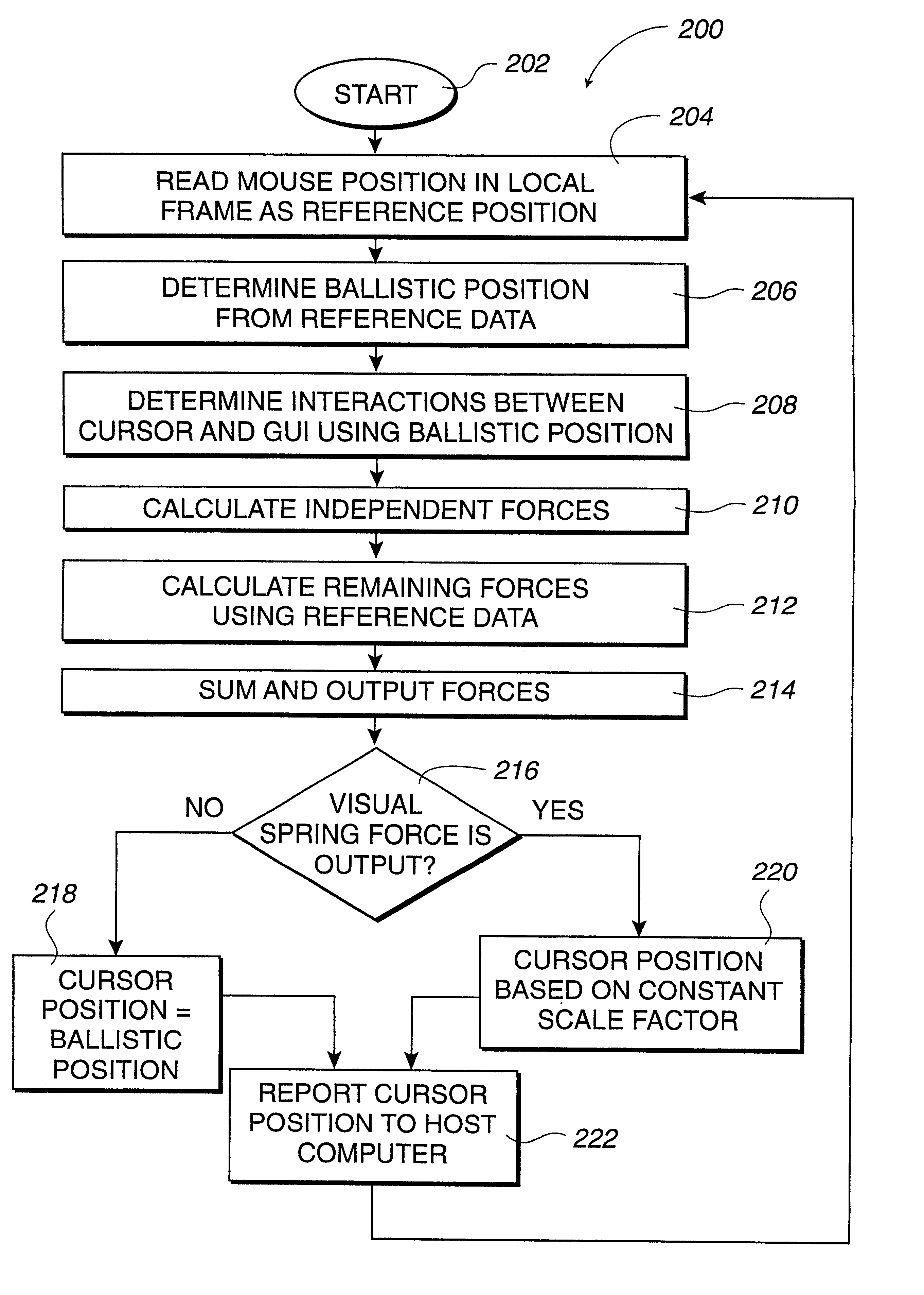
[0019]More specifically, a method of the present invention provides enhanced cursor control using a force feedback interface device coupled to host computer. The host computer displays a cursor within a graphical environment, such as a GUI, on a display device. A position of a user-grasped manipulandum, such as a mouse, in a device workspace is read as a reference position. A cursor position is reported to the host computer derived from the reference position, and the host computer displays the cursor within the graphical environment at a position corresponding to the cursor position. It is determined whether the cursor interacts with the graphical environment as to cause a force to be output on the manipulandum, and, if so, a force is output on the manipulandum. At least one of the reported cursor position and the output force allows the user of the force feedback interface device to finely position the cursor within the graphical environment and coarsely move the cursor in the graphical environment without causing a distortion in the output forces as expected to be experienced by the user.
[0021]In other embodiments, enhanced cursor control is provided by outputting assistive forces. In one embodiment, a resistive force dedicated for enhanced cursor control, such as a damping for friction force, is output to slow movement of the manipulandum. The resistive force has a magnitude inversely based on a velocity of the manipulandum in the device workspace to allow the mouse to be slowed down for fine positioning tasks and freed or unencumbered for coarse positioning tasks. In a different embodiment, a detent force is associated with targets in the GUI for guiding the manipulandum to a particular position and thereby guiding said cursor to a corresponding position in the graphical environment. In another embodiment, the detent forces are provided as a field of detents arranged in a predetermined spacing over a predetermined area surrounding the cursor, which are provided when the manipulandum is under a predetermined velocity and thus likely to need the detents for fine positioning of the cursor. In a different embodiment, obstruction forces simulating surfaces are arranged to assist the user to controlling the cursor in fine positioning tasks.
[0025]The methods and apparatus of the present invention advantageously provides enhanced control over a cursor in a graphical environment while not compromising the fidelity or expected feel of force feedback sensations based on motion of the mouse or other user object. This allows a user to perform fine positioning and coarse motion of the cursor as desired and still experience forces as expected based on interactions of the cursor in the graphical environment. In addition, the indexing features of the present invention allow the user to control the cursor even when a large offset exists between the mouse and cursor positions in their respective frames, allows the user to reduce this offset, and substantially reduces the user's undesired experience of any hard, physical stops when the mouse reaches a physical limit.

Problems solved by technology

However, a problem occurs in mouse-type devices when the user wishes to move the cursor a short distance or in small increments (“fine positioning”).
For tasks in which accurate positioning of the cursor is needed, such as target acquisition tasks, the large scaling of mouse movement to cursor movement is inadequate or even harmful.
If very small motions of the mouse result in large cursor motion, the user may simply lack the manual dexterity to acquire the target.
Certain target acquisition tasks where the targets are very small can be particularly challenging even if the mapping between the cursor and the mouse is reasonable for most other cursor motion activities.
For such situations, a scaling that causes large motions of the cursor for small motions of the mouse may make a target acquisition task physically impossible for the user.
A problem occurs when standard ballistics techniques are used with force feedback interface devices.
When these and other types of forces are implemented in conjunction with mouse ballistics, a conflict occurs between the use of ballistics position and force feedback output.
Thus, when implementing forces in an interface device, motion of the mouse can no longer be consistently correlated to cursor motion on the screen due to the variable scaling.
This is a particular problem for a force feedback mouse system because in general, feel sensations such as springs, surfaces, dampers, textures, masses, and other spatially related physical phenomenon rely on a constant, predictable mapping between the motion of the mechanical object (mouse), the forces generated on the mouse, and graphically displayed interactions on the screen (cursor motion).
If no ballistics are in effect, no problem exists because the cursor displacement used in the visual display has a consistent, constant mapping to the mouse displacement used in the force “display.” However, if ballistics are used to map physical mouse motion to displayed cursor motion, the motion of the cursor varies depending upon mouse velocity, causing a potential conflict: the stretch displayed visually is based on the variable mapping adjusted by the ballistic algorithm, while the stretch force is based on pure mouse motion.
This conflict becomes a problem when, for example, the user stretches a line very quickly in one direction from a starting position (both a mouse starting position and a screen starting position), changes to the opposite direction, and unstretches the line very slowly toward the starting position.
However, on a force feedback mouse where force display is based on mouse motion and visual display is based on cursor motion, a disconcerting dichotomy is noticed by the user.
Thus a problem is evident in force feedback mouse-type devices: ballistics are needed to allow dexterous cursor control, yet ballistics distorts the seeing-feeling relationship.
Thus, adjusting the mapping between physical mouse motion and displayed cursor motion makes sense for graphical display, but does not make sense for force feedback where physical realism is critical to effective sensation generation.
Unfortunately, such a force feedback mouse would not be optimized for both fine positioning and coarse motion, as is true of traditional mice.
In addition, mouse ballistics causes another problem that causes difficulty in force feedback mouse implementation.
If this offset becomes too large, the user may not be able to reach some parts of the screen within the range of motion of the mouse.
A force feedback mouse may have a limited workspace due to cost constraints and may not be able to be lifted off the table and repositioned.
In addition, the mouse hitting a physical limit to its workspace is disconcerting for a user expecting realistic force feedback.
Thus, traditional indexing may not be practical.

Method used


Image

  • Cursor control using a tactile feedback device
  • Cursor control using a tactile feedback device
  • Cursor control using a tactile feedback device

Examples


Embodiment Construction

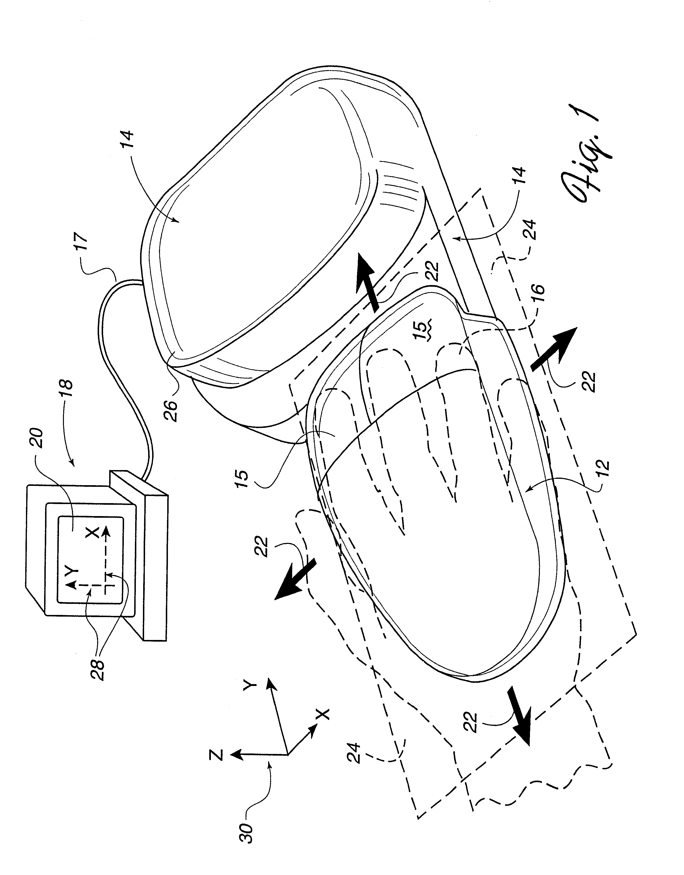
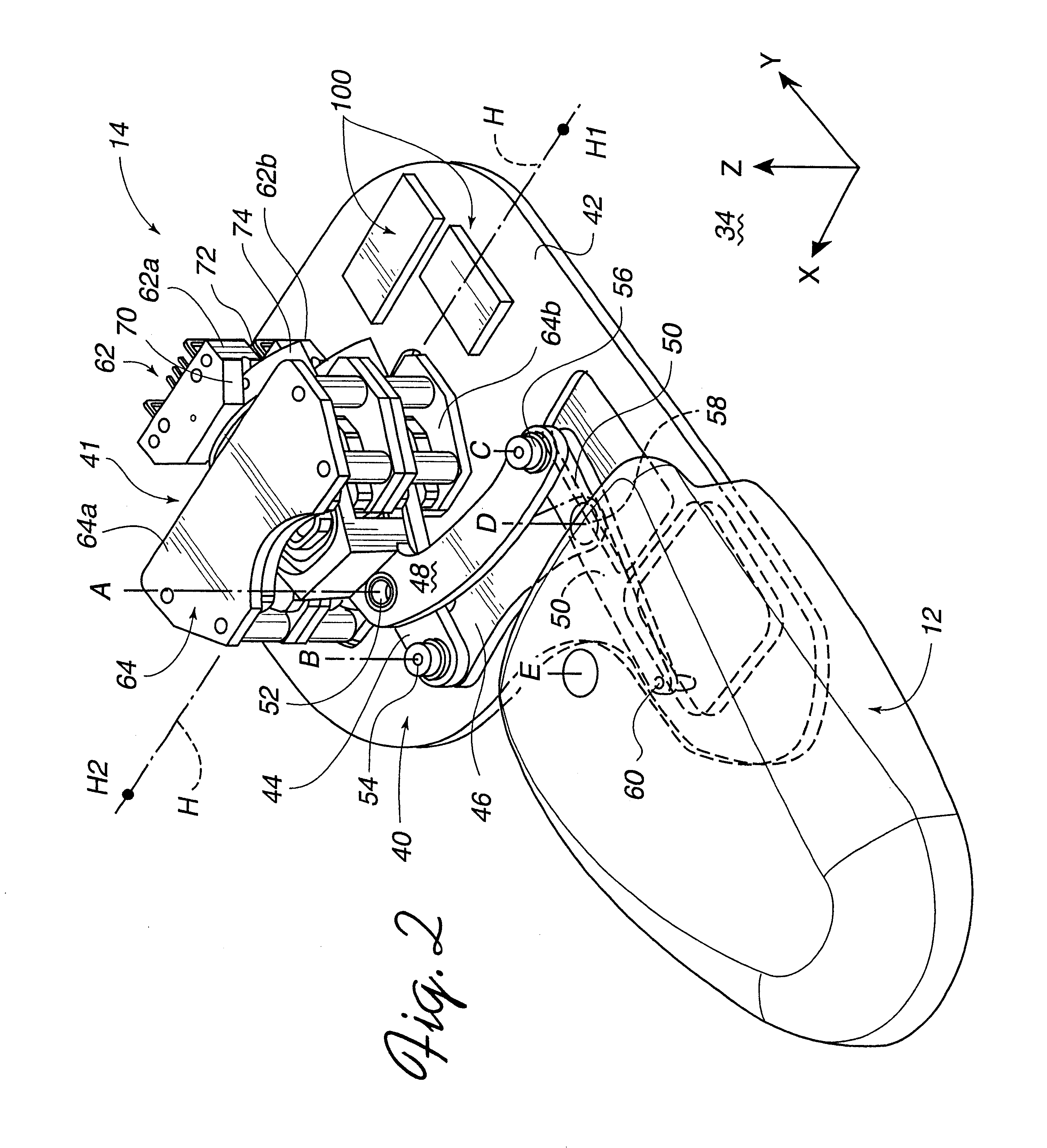
[0041]FIG. 1 is a perspective view of a force feedback mouse interface system 10 of the present invention capable of providing input to a host computer based on the user's manipulation of the mouse and capable of providing force feedback to the user of the mouse system based on events occurring in a program implemented by the host computer. Mouse system 10 includes a mouse or “puck”12, an interface 14, and a host computer 18. It should be noted that the term “mouse” as used herein, indicates an object 12 generally shaped to be grasped or contacted from above and moved within a substantially planar workspace (and additional degrees of freedom if available). Typically, a mouse is a smooth or angular shaped compact unit that snugly fits under a user's hand, fingers, and / or palm, but may be shaped otherwise in other embodiments.

[0042]Mouse 12 is an object that is preferably grasped or gripped and manipulated by a user. By “grasp,” it is meant that users may releasably engage a portion o...


PUM


Abstract

A mouse interface device and method for providing enhanced cursor control and indexing cursor control with force feedback. A force feedback interface device includes a manipulandum, such as a mouse, that is moveable in a local workspace. The device is coupled to a host computer that displays a cursor in a graphical environment, such as a GUI, on a display screen. A cursor position in the display frame is reported to the host computer derived from a reference position of the mouse in the local frame, and the host displays the cursor; for example, the cursor position may be scaled by a ballistics algorithm based on mouse velocity to allow fine positioning or coarse motion of the cursor. A force is output on the mouse based on interactions in the GUI, the force being determined based on mouse reference data or cursor ballistic data, depending on the type of force, to reduce distortion between visual and force outputs. Assistive forces can alternatively be output to achieve the enhanced cursor control. Indexing features allow control of the cursor when an offset between local and display frames exists, allow the user to reduce the offset, and reduce disconcerting collisions of the mouse with physical workspace limits.

Description

[0001]This application is a continuation of application Ser. No. 09 / 343,940, filed Jun. 30, 1999, U.S. Pat. No. 6,288,705 entitled “Interface Device and Method for Providing Indexed Cursor Control with Force Feedback,” which is a divisional of application Ser. No. 09 / 924,462, filed Aug. 23, 1997, now U.S. Pat. No. 6,252,579, both of which are incorporated herein by reference in their entireties.[0002]This invention was made with Government support under Contract Number F41624-96-C-6029 awarded by the Department of Defense. The Government has certain rights in this invention.BACKGROUND OF THE INVENTION[0003]The present invention relates generally to interface devices for allowing humans to interface with computer systems, and more particularly to computer interface devices that allow the user to provide input to computer systems and provide force feedback to the user.[0004]Computer systems are used extensively to implement many applications, such as word processing, data management, ...

Claims


Application Information

Patent Timeline
IPC IPC(8): G06F3/00G06F3/033G06F3/01G06F3/038G06F3/042
CPCG06F3/016G06F3/0354G06F3/038G06F3/03548G06F2203/015G06F2203/014
Inventor ROSENBERG, LOUIS B.BEAMER, JONATHAN L.BRAUN, ADAM C.CHANG, DEAN C.
Owner IMMERSION CORPORATION
Learn More