Rotary sheeter having an improved vacuum means for cross trim removal

a vacuum means and cross trim technology, applied in the field of apparatus for cutting and removing trim strips, can solve the problems of insufficient simply cutting the web, non-printed area formed in each revolution of the printing press, and unsightly bleed area, etc., and achieve the effect of economic, simple and effectiv

Inactive Publication Date: 2005-05-24
ADVANCE GRAPHICS EQUIP OF YORK
View PDF23 Cites 10 Cited by
  • Summary
  • Abstract
  • Description
  • Claims
  • Application Information

AI Technical Summary

Benefits of technology

[0008]It is, therefore, a primary object of the present invention to provide an apparatus for continuously cutting and removing trim strips from a moving web which is economical, simple and effective.
[0009]It is also an object of the present invention to provide an apparatus for continuously cutting and removing trim strips from a moving web which removes cut trim strips through the use of a slotted cylinder having a low pressure applied to the slot and which avoids blade fouling and clogging of the cutting area.
[0012]It is still another object of the present invention to provide an apparatus for continuously cutting and removing trim strips from a moving web wherein the slotted hollow cylinder is driven by the shaft mounting the trim strip cutting knives for positioning the slot at the leading edge of the web at the time that the trim strip is cut for immediate and efficient removal of the trim strip via vacuum means in the hollow cylinder communicating with the slot, after which the slot rotates away from the leading edge of the web to avoid drawing the leading edge of the web into the slot.
[0022]In still another aspect of the invention, there is provided an apparatus for continuously cutting a web and removing trim strips therefrom wherein the knife means comprises one pair of circumferentially spaced apart knives, the hollow cylinder is rotationally driven relative to the cutting shaft at a ratio of two revolutions of the cylinder for each revolution of the cutting shaft and the apparatus includes exit means for engaging the web and moving the web away from the cutting area, the leading edge of the web being engaged by the exit means before the opening communicates with the cutting area during the second revolution of the cylinder for providing a tension on the web preventing the reduced pressure at the opening from drawing a portion of the web upstream of the leading edge into the opening.

Problems solved by technology

However, it is commonly found that at the lines of intersection of these images, a bleed area forms which is somewhat unsightly and which should be removed.
Furthermore, there is always a non-printed area formed in each revolution of the printing press, due to the lock-up mechanism holding the two ends of the printing plate or blanket wrapped around the plate or blanket cylinder.
For these purposes, it is not sufficient simply to cut the web.
However, such apparatuses have proven to be functionally and / or economically inefficient, by failing to prevent clogging of the cutting area and or requiring expensive and / or numerous mechanically operated components.
A disadvantage of this type of apparatus is that it is expensive to build the trim strip removal structure into the interior of the rotatable cutting cylinder.
In addition, the opening between the knives is a relatively small space and it is difficult for cut trim strips to pass through it.
As a result, the cut trim strips can easily get caught up on and foul the cutting knives or clog the opening and, eventually, impede the cutting ability of the knives and / or cause a shut down of the cutting cylinder.
The disadvantage of this type of arrangement is that it requires both negative and positive air flows at the strip to assure trim strip removal while preventing the leading edge of the web from following the trim strip into the slot.
Notwithstanding these and other efforts to efficiently cut and remove trim strips from printed webs, it should be apparent that efforts to date suffer from one or more shortcomings which make the apparatus unnecessarily complicated, expensive or unreliable in use.

Method used


Image

  • Rotary sheeter having an improved vacuum means for cross trim removal
  • Rotary sheeter having an improved vacuum means for cross trim removal
  • Rotary sheeter having an improved vacuum means for cross trim removal

Examples


Embodiment Construction

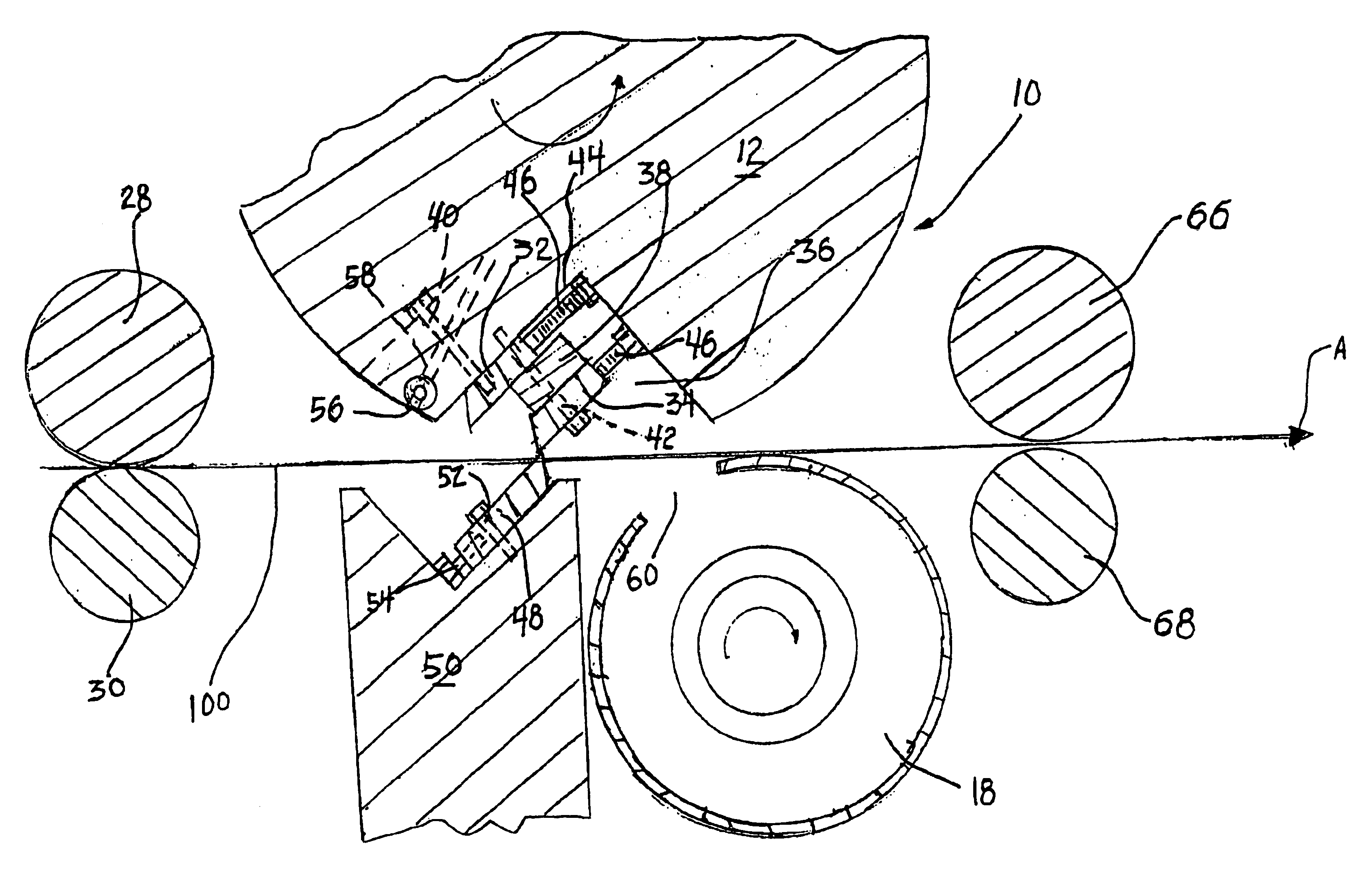
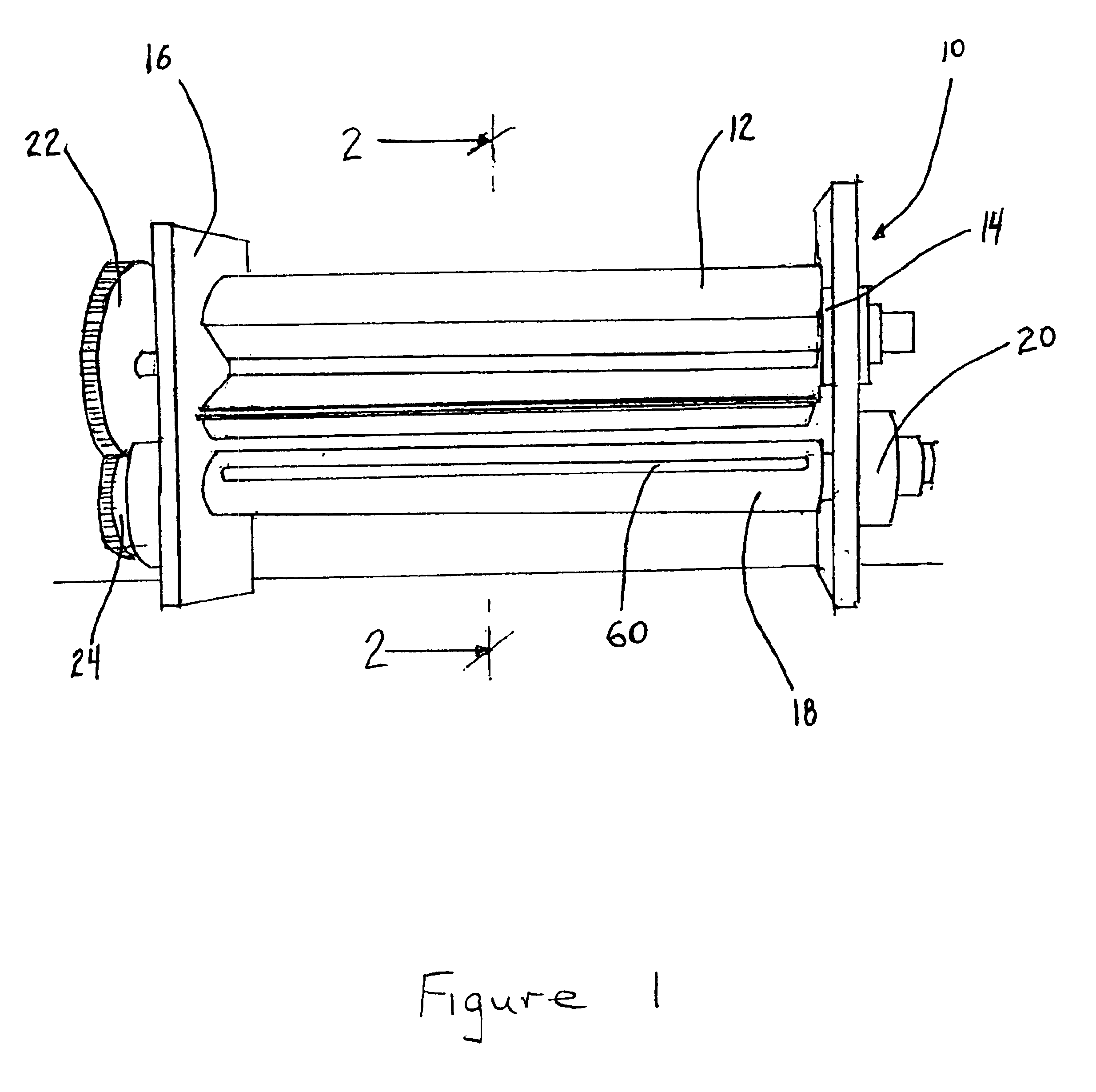
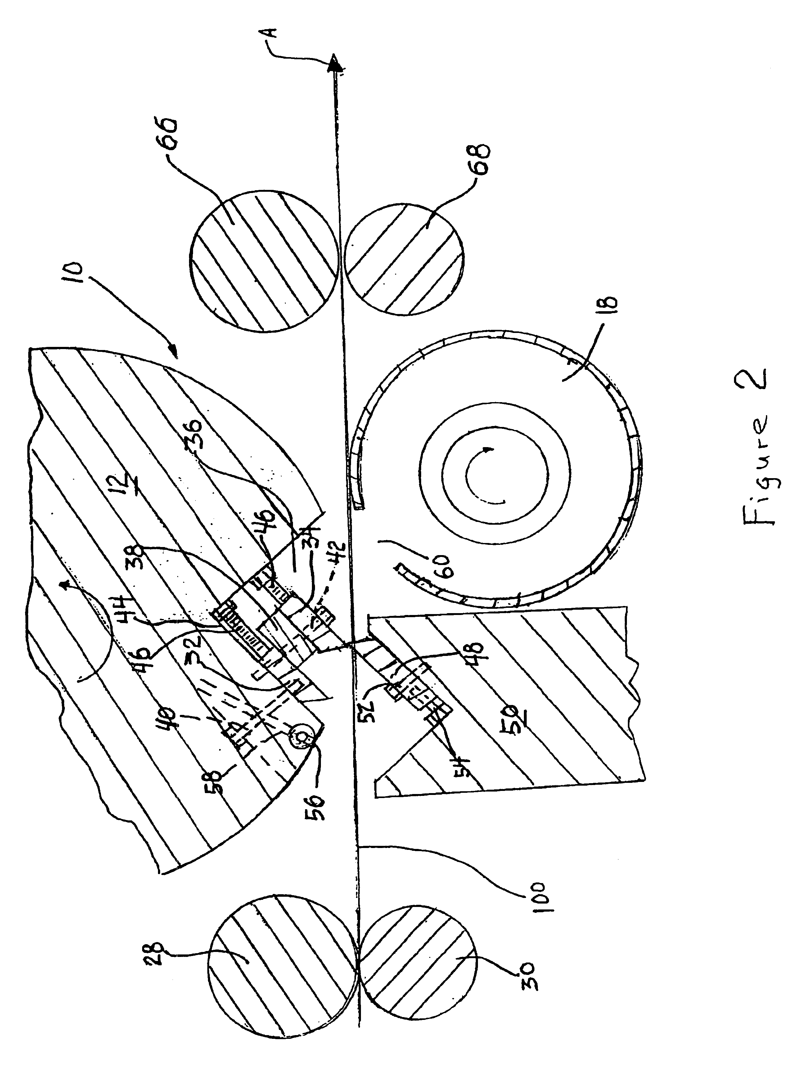
[0028]The trim strip cutting apparatus 10 of the present invention is illustrated in FIG. 1 and comprises a cutting shaft 12 mounted for rotation on its opposed sides in bearings 14 which are supported by frame 16. Also mounted in frame 16 is a slotted, hollow cylinder 18 mounted for rotation on its opposed sides in bearings 20. A cutting shaft gear 22 is fixed at one end of the cutting shaft 12 to enable the cutting shaft 12 to be driven, through a drive train by an electric motor (not shown). A rotating cylinder gear 24 is fixed at one end of the slotted cylinder 18 and meshes with the teeth on cutting shaft gear 22 to enable the slotted cylinder 18 to be driven by the rotating cutting shaft 12.

[0029]Trim strip cutting apparatus 10 is typically positioned in-line with the output end of a rotary web press for cutting printed webs coming off the web press. Any number of post-web press operational units may be positioned between the web press and the trim strip cutting apparatus to p...


PUM

PropertyMeasurementUnit
circumferential lengthaaaaaaaaaa
lengthsaaaaaaaaaa
speedaaaaaaaaaa

Abstract

Apparatus for continuously cutting a web and removing trim strips therefrom, including a pair of circumferentially spaced knives supported on a cutting shaft, the shaft being rotationally mounted for cutting, in a cutting area, the web transverse to its direction of movement for forming trim strips, a cylinder mounted along the underside of the web for rotation about an axis which is generally perpendicular to the direction of the moving web, the cylinder having a hollow bore communicating with a low pressure source and an opening formed in the surface of the cylinder communicating with the bore for providing low pressure at the opening, the cylinder being rotated at a predetermined speed such that the opening is positioned in the cutting area immediately downstream of the knives each time a trim strip is cut from the web and the opening is rotated away from the cutting area immediately thereafter.

Description

CROSS-REFERENCE TO RELATED APPLICATIONS[0001]This is a non-provisional application based upon U.S. provisional application Ser. No. 60 / 476,240, filed Jun. 6, 2003, now pending.FIELD OF THE INVENTION[0002]The present invention relates to apparatus for cutting and removing trim strips from a printed web and, more particularly, to an apparatus which will cut trim strips from a moving printed web in a continuous manner and remove the trim strips from the cutting area using air flow.BACKGROUND OF THE INVENTION[0003]In early web product processing systems, the web coming from a web press was simply cut into sheets of uniform size, stacked, and sent to a bindery where further operations would take place on the sheets, including further cutting, trimming, gluing, and folding. Technological advancements in the field have simplified the processing of web products by incorporating the slitting, trimming, and folding operations as functions carried out at the exit end of the web press on the pr...

Claims


Application Information

Patent Timeline
Patent Type & Authority Patents(United States)
IPC IPC(8): B26D7/18
CPCB26D7/1863B26D7/1854Y10T83/207Y10T83/4836Y10T83/4847
Inventor SNYDER, DENNIS L.
Owner ADVANCE GRAPHICS EQUIP OF YORK
Why Eureka
Try Eureka