Deformable member

a technology of deformation and member, applied in the direction of pipe elements, fluid removal, mechanical equipment, etc., can solve the problems of inability to reuse seals, complex metal-to-metal seals, and lack of metal-to-metal seals strength

Inactive Publication Date: 2005-05-24
ZEROTH TECH
View PDF10 Cites 278 Cited by
  • Summary
  • Abstract
  • Description
  • Claims
  • Application Information

AI Technical Summary

Benefits of technology

[0008]It is amongst the objects of the present invention to obviate or mitigate at least one of the foregoing disadvantages. Embodiments of the inventi

Problems solved by technology

Such metal to metal seals are complex, expensive to manufacture, must be preformed and often result in permanent deformation so that the seals cannot be reused.
Also, it is known to provide resilient seals which do not provide metal to metal sealing in such tubing, are cheap and which are reusable, however, such resilient seals have disadvantages that they do not have the strength of metal to metal seals and cannot be used in aggressive environments which degrade the seal.
Each of such tools are often complex, including many interrelated parts, and require complex running, support, activating/deactivating and retrieving tools to achieve sealing and allow the well operation to be carried out using the tool.
Furthermore, complex operations are often required to be performed in order to locate, activate/deactivate and/or retrieve the tools.
Sim

Method used


Image

  • Deformable member
  • Deformable member
  • Deformable member

Examples


first embodiment

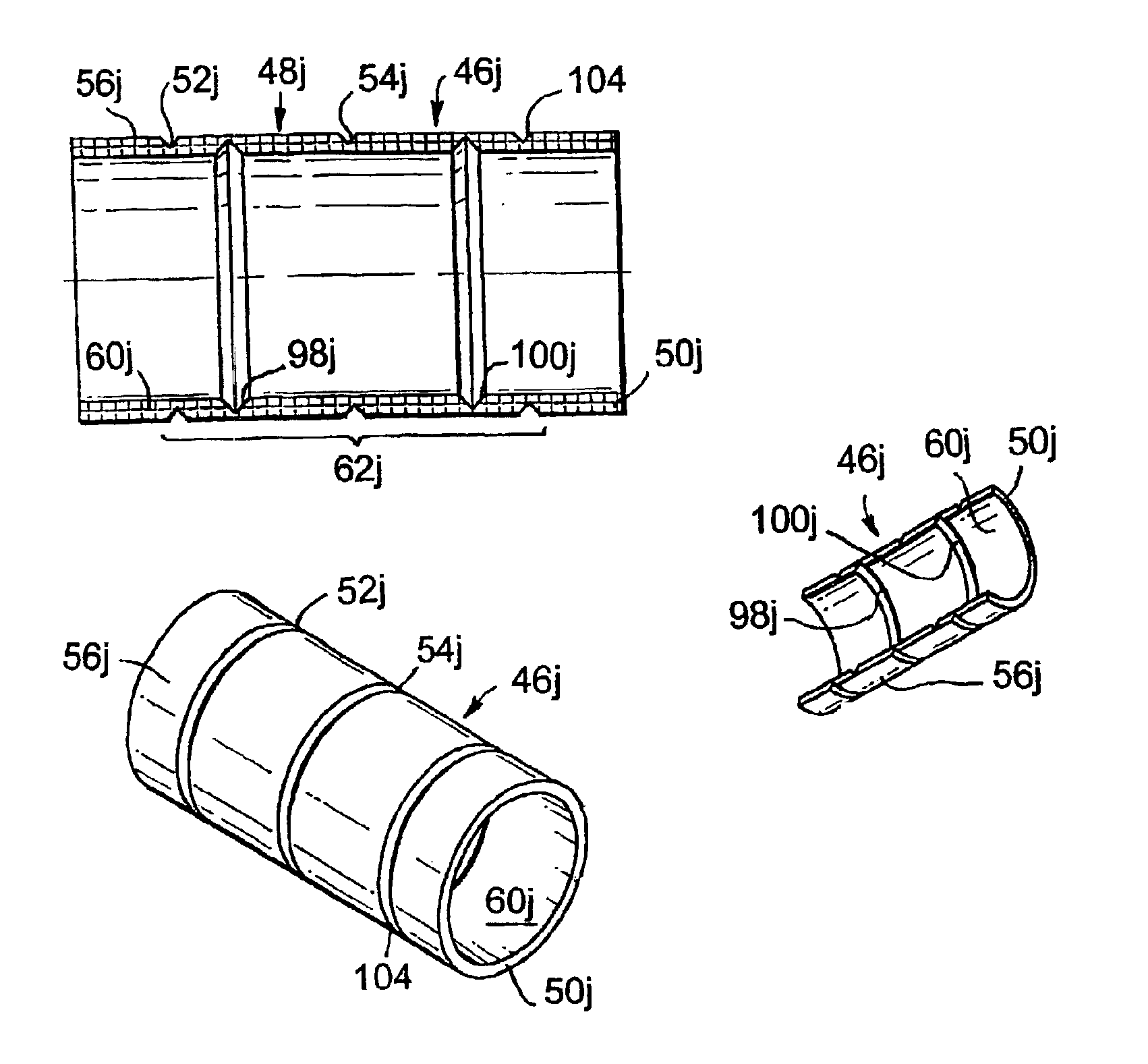
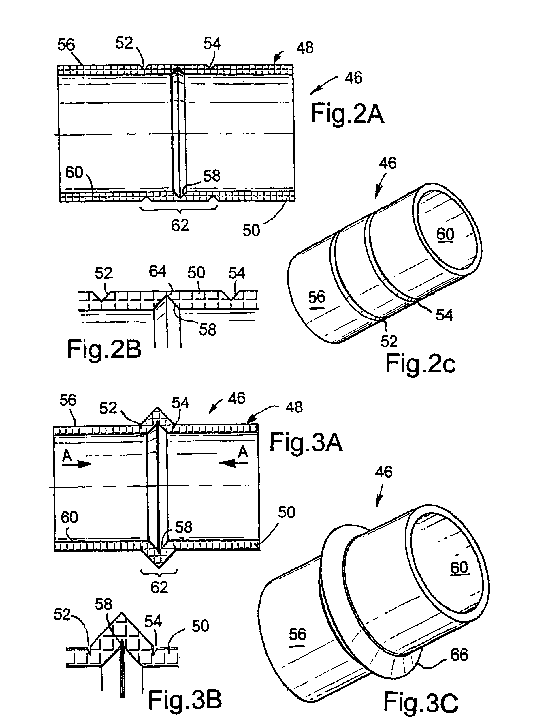
[0147]Turning initially to FIGS. 2A to 3C, there is shown a deformable member indicated generally by reference numeral 46, in accordance with the present invention. The deformable member 46 is shown in FIGS. 2A to 2C in an undeformed position, and comprises a generally hollow cylindrical body 48 defining a wall 50 of the member 46. The wall 50 includes three circumferential lines of weakness in the form of grooves, spaced equidistantly along the wall 50, with two grooves 52 and 54 provided in an outer surface 56 of the member wall 50, and the other groove 58 provided in an inner surface 60 of the member wall 50. Each of the grooves 52,54 and 58 are substantially V-shaped in cross-section and are formed in the deformable member by a finishing process such as a milling or turning operation.

[0148]The deformable member 46 is hollow to allow the member to be located on a supporting member such as an inner mandrel or sleeve (not shown), to form part of a well tool or the like for running ...

second embodiment

[0167]FIGS. 4A to 5C show a deformable member indicated generally by reference numeral 46a, in accordance with the present invention. The grooves 52a and 54a are provided in an inner surface 60a of a wall 50a of the member 46a, and the groove 58a is provided in an outer surface 56a of the member wall 50a. The grooves 52a and 54a define the zone of deformation 62a of the member 46a. The groove 58a in the member wall outer surface 56a extends to a depth greater than half the wall 50a thickness, in a similar fashion to the groove 58 in member 46.

[0168]In this fashion, when an axial force is applied in the direction of the arrows A shown in FIG. 5A, the member 46a is deformed inwardly, to engage a tube (not shown) located within the deformable member 46a. This deformation occurs in the same fashion as for the deformable member 46 of FIGS. 2A to 3C, forming a circumferential edge 66a, shown in FIG. 5C, for engaging the tube.

[0169]The deformable member 46a has numerous applications in dow...

third embodiment

[0170]FIGS. 6A to 7C show a deformable member indicated generally by reference numeral 46b, in accordance with the present invention. The deformable member 46b includes two grooves 52b and 54b provided in an outer surface 56b of a wall 50b of the member 46b, similar to the grooves 52 and 54 in the member 46. The other line of weakness defines a channel 68, shown more clearly in the enlarged view of FIG. 6B. The channel 68 has a substantially flat base 70 with inclined side walls, and is provided in an inner surface 60b of the member wall 50b. A further circumferential groove 74, substantially V-shaped in cross section, similar to the grooves 52,54 and 58 of member 46, is provided in the flat base 70 of the channel 68.

[0171]When the member 46b is deformed on application of an axial force A, shown in FIG. 7A, the profile of the channel 68 causes a lip 77, best shown in FIGS. 7B to 7D, to be formed at a radially outer extreme of the member 46b, in the region of the deformation zone 62b...


PUM

PropertyMeasurementUnit
Thicknessaaaaaaaaaa
Forceaaaaaaaaaa
Pressureaaaaaaaaaa

Abstract

A deformable member can be used in a well tool for use in downhole oil/gas wells. In one embodiment, a deformable member (46) is described which is deformable between undeformed and deformed positions, and comprises a generally hollow cylindrical body (48) defining a wall (50). The wall (50) includes three circumferential lines of weakness in the form of grooves, with two grooves (52, 54) provided in an outer surface (56) of the member wall (50), and the other groove (58) provided in an inner surface (60). The member (46) is deformed outwardly by folding about the lines of weakness (52, 54, 56) and is used in particular to obtain sealing contact with a tube in which the member (46) is located.

Description

RELATED APPLICATIONS[0001]This is a Continuation under 35 USC 120 of PCT / GB01 / 03072, filed Jul. 9, 2001, which published in English as WO 02 / 04783, and whose contents are incorporated by reference.BACKGROUND[0002]The present invention relates to a deformable member. Particularly, but not exclusively, the present invention relates to a deformable member for use in a well tool, especially for providing a metal to metal seal, and to a well tool with a deformable member.[0003]It is known to provide metal to metal seals to carry out a wide variety of sealing operations within tubing such as surface fluid pipe lines and well tubing of an oil or gas well. Such metal to metal seals are complex, expensive to manufacture, must be preformed and often result in permanent deformation so that the seals cannot be reused. Also, it is known to provide resilient seals which do not provide metal to metal sealing in such tubing, are cheap and which are reusable, however, such resilient seals have disad...

Claims


Application Information

Patent Timeline
IPC IPC(8): B21D15/00B21C37/20B21D15/06B21C37/15E21B29/00E21B23/00E21B33/12E21B29/08E21B23/01B21C37/16B21C37/28B21D17/02B21D39/20E21B23/06E21B33/00E21B33/128E21B43/10F16L55/136
CPCB21C37/16F16L55/136B21C37/28B21D15/06B21D17/025B21D39/203E21B23/01E21B23/06E21B29/08E21B33/12E21B33/1212E21B33/128E21B43/10E21B43/103E21B43/106B21C37/205E21B2033/005E21B2200/01
Inventor MOYES, PETER BARNES
Owner ZEROTH TECH
Why Eureka
Try Eureka