
Arthroscopic suture passing instrument

a technology of arthroscopic surgery and passing instruments, which is applied in the field of surgical suture passing instruments, can solve the problems of arthroscopic surgery, no independent control of the instrument's suture engagement with the hook, and relatively large instruments

Inactive Publication Date: 2005-05-24
ARTHREX
View PDF16 Cites 337 Cited by
  • Summary
  • Abstract
  • Description
  • Claims
  • Application Information

AI Technical Summary

Benefits of technology

The present invention provides an arthroscopic suturing instrument that overcomes the disadvantages of prior art. The instrument includes a shaft with a proximal end and a distal end. A jaw is disposed on the distal end of the shaft, which takes the form of a needle with a hook. The jaw opens and closes in relation to the distal end of the shaft. A handle disposed on the proximal end of the shaft operates to open and close the jaw. The instrument also includes a slidable suture shuttle on the distal end of the shaft, which is controlled by a trigger near the handle. The shuttle is moved to hold a length of suture in a slot on the shuttle away from the hook when the jaw is closed and tissue is pierced with the needle. The instrument is advanced towards tissue to be repaired, and the needle is pressed through tissue by closing the jaw using the instrument handles. The suture shuttle is moved back into position so as to load the suture onto the hook. Opening the jaw and withdrawing the needle from the tissue pulls a loop of suture through the tissue, which is then available for further suturing or knot tying. The technical effects of this invention include improved suturing precision, reduced risk of complications, and simplified procedure for arthroscopic surgery.

Problems solved by technology

This instrument is relatively bulky, which is disadvantageous for arthroscopic surgery.
In addition, the instrument has no independent control over whether the suture engages the hook once the jaws are closed.

Method used


Image

  • Arthroscopic suture passing instrument
  • Arthroscopic suture passing instrument
  • Arthroscopic suture passing instrument

Examples


Embodiment Construction

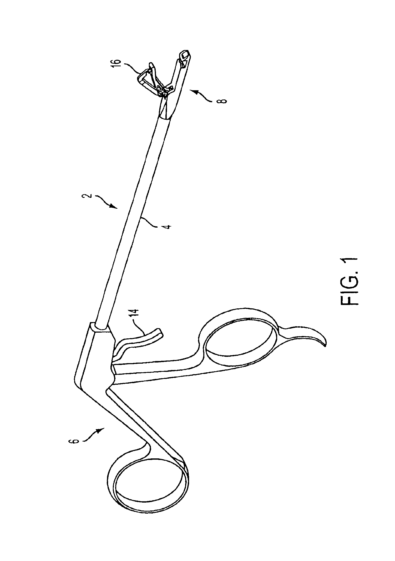
[0026]Referring initially to FIG. 1, a preferred embodiment of an arthroscopic suture passing instrument 2 according to the present invention is shown in a perspective view. Hand instrument 2 includes a shaft 4 connecting a handle 6 disposed proximally to an operative jaw 8 disposed distally.

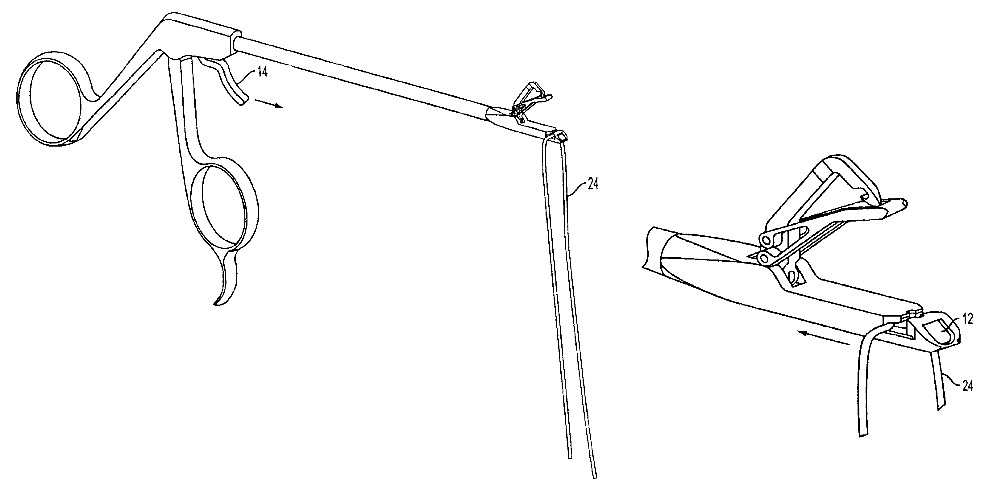
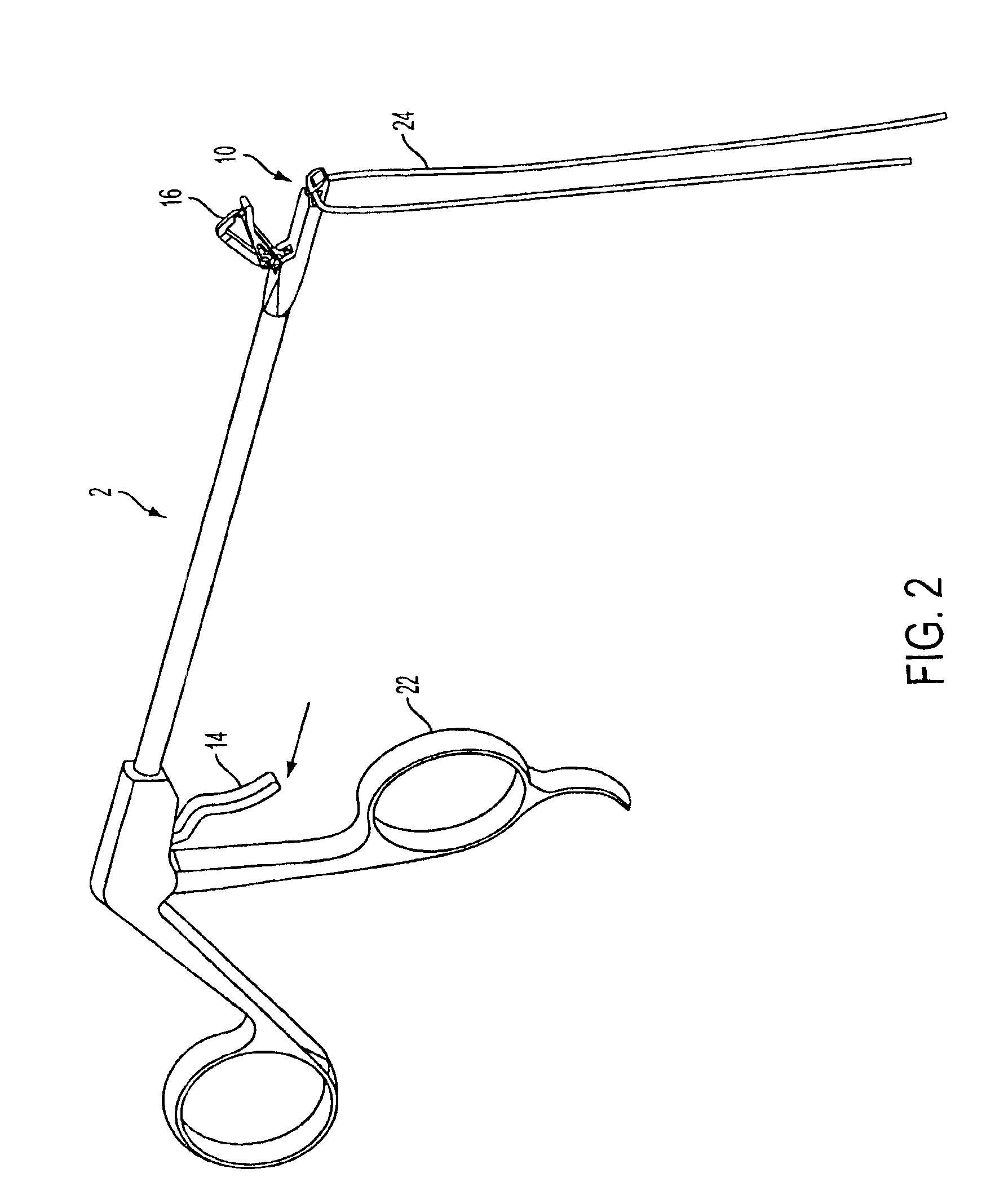
[0027]Referring also to FIGS. 2 and 3, hand instrument 2 includes a slot 10 formed at the distal end. A slidable suture shuttle 12, shown in a forward position in FIG. 3, controls access to slot 10. Suture shuttle 12 is operated using trigger 14, which is connected to the suture shuttle by a control rod (not shown), for example.

[0028]The structure and function of the suture shuttle will be explained in more detail below in connection with a preferred method of suture passing according to the present invention.

[0029]Operative jaw 8 includes a needle 16. A hook 18 is formed toward the pointed tip of needle 16. A spring arm 20 pivots to urge tissue off of needle 16 as the jaws are opened by way of ...


PUM


Abstract

An instrument for arthroscopic suture passing having a shaft with a proximal end and a distal end. A jaw disposed on the distal end has a needle and a hook. The jaw opens and closes with respect to a stationary distal tip of the instrument. A handle disposed on the proximal end manipulates the jaw. A movable suture shuttle is disposed in the distal tip of the instrument. Arthroscopic suture passing takes place by initially loading a length of suture into the suture shuttle, and capturing the suture by moving the suture shuttle away from a position in which it would engage the needle and hook. The needle then is advanced through tissue using the handle to close the jaw against the stationery tip. The suture shuttle then is advanced to load the suture onto the hook. Opening the jaw draws the needle back through the tissue, pulling the suture in a loop through the tissue. A spring arm urges tissue off of the needle. The loop of suture then is available for further suturing or knot tying.

Description

[0001]This application claims the benefit of U.S. Provisional Patent Application Ser. No. 60 / 278,004 filed Mar. 23, 2001.BACKGROUND OF THE INVENTION[0002]1. Field of the Invention[0003]The present invention relates to a surgical suture passing instrument, and more specifically to a hand instrument for passing suture in arthroscopic tissue repair procedures.[0004]2. Brief Description of the Related Art[0005]Arthroscopic reattachment, of a rotator-cuff tendon for example, often requires the surgeon generally to attach a length of suture material remotely to an internal body part, and then to secure the suture to another part. In a typical example, suture is passed through a detached tendon and is then secured to a hole or anchor in a bone. Various instruments have been developed for this purpose. U.S. Pat. No. 5,522,820 to Caspari describes a suture instrument that has a pair of relatively-movable jaws. A piercing needle with a hook is fixed to one of the jaws. The other jaw holds a l...

Claims


Application Information

Patent Timeline
Patent Type & Authority Patents(United States)
IPC IPC(8): A61B17/04A61B17/06
CPCA61B17/0469A61B2017/06042
Inventor WEBER, ROBERT M.
Owner ARTHREX
Learn More