Compound injection molded high pressure laminate flooring

a technology of laminate flooring and high pressure, applied in the direction of transportation and packaging, other domestic articles, and cellulosic plastic layered products, etc., can solve the problems of reducing the production capacity of the remaining line, limiting the production capacity of the remaining line, and reducing the production capacity of the entire processing lin

Inactive Publication Date: 2005-05-24
PREMARK RWP HLDG
View PDF16 Cites 2 Cited by
  • Summary
  • Abstract
  • Description
  • Claims
  • Application Information

AI Technical Summary

Problems solved by technology

As such, a breakdown occurring at any point in the line results in the shutdown of the entire processing line until such a time that the problem is corrected.
The use of line processing further limits production capabilities, and necessitates a substantial investment in updating or replacing equipment segments within a processing line once the capacity of a given equipment segment reaches its production limit.
For example, if a packaging segment in a flooring plank processing line is capable of packaging 36 boxes of 8 planks per hour, the remainder of the line is limited to this capacity regardless of whether other equipment segments are capable of a greater output.
However, increased speed is not always an answer to the need for increased production.
When a processing line is pushed to its limits, it is more likely to break down, resulting in down time.
In addition, where a processing line is operating at maximum capacity, for example, 100 flooring planks per minute, errors in processing result in the disposal of all items processed during a given time period.
Extensive and expensive cutting tools are used in converting these large panels into multiple planks, as well as in machining the required edge profile into the flooring planks.
The extensive use of cutting tools adds substantial time and expense to the manufacturing process.
In addition, the cutting tools are preferably diamond tipped and maintenance of these diamond tipped cutting tools adds substantial expense to the manufacturing process.
In addition to the cost and maintenance problems associated with the use of conventional cutting tools in the manufacture of flooring planks, the use of cutting tools limits the possible edge profiles that may be formed on the flooring planks.
These limitations in turn restrict the possible designs which might be used to improve the functionality, repairability and installability of flooring planks.
This generates substantial and undesirable waste.
The use of current manufacturing techniques severely limits possible variations which might improve the structural characteristics of the flooring planks.
For example, the core or substrate materials commonly used in conventional flooring planks are wood-based and, therefore, susceptible to the effects of moisture.
Moisture renders wood-based substrates highly susceptible to warping, shrinkage, and separation between the decorative laminate wear surface, backer layer and the core.
Since current flooring plank manufacturing techniques have been developed to primarily handle wood-based core materials, their adaptation for manufacturing flooring planks utilizing alternate, waterproof, core materials is thought to be impractical.
In addition to the water damage to which wood-based flooring planks are susceptible, the use of wood-based core materials substantially extends the time required for producing flooring planks.
The extended sitting periods further leave the core materials and finished flooring planks susceptible to damage during the time in which they are required to sit.
For example, core sheets are often permanently bent or warped during storage and must be thrown away.
Damage to the formed panels and / or planks is also encountered as a result of the many steps involved in the production thereof.
As those skilled in the art will certainly appreciate, the components of the panel are moved many times during production of a flooring plank and each time the panel, or the components thereof, are moved, there is a chance that damage will occur.

Method used


Image

  • Compound injection molded high pressure laminate flooring
  • Compound injection molded high pressure laminate flooring
  • Compound injection molded high pressure laminate flooring

Examples


Embodiment Construction

[0036]The detailed embodiments of the present invention are disclosed herein. It should be understood, however, that the disclosed embodiments are merely exemplary of the invention, which may be embodied in various forms. Therefore, the details disclosed herein are not to be interpreted as limited, but merely as the basis for the claims and as a basis for teaching one skilled in the art how to make and / or use the invention.

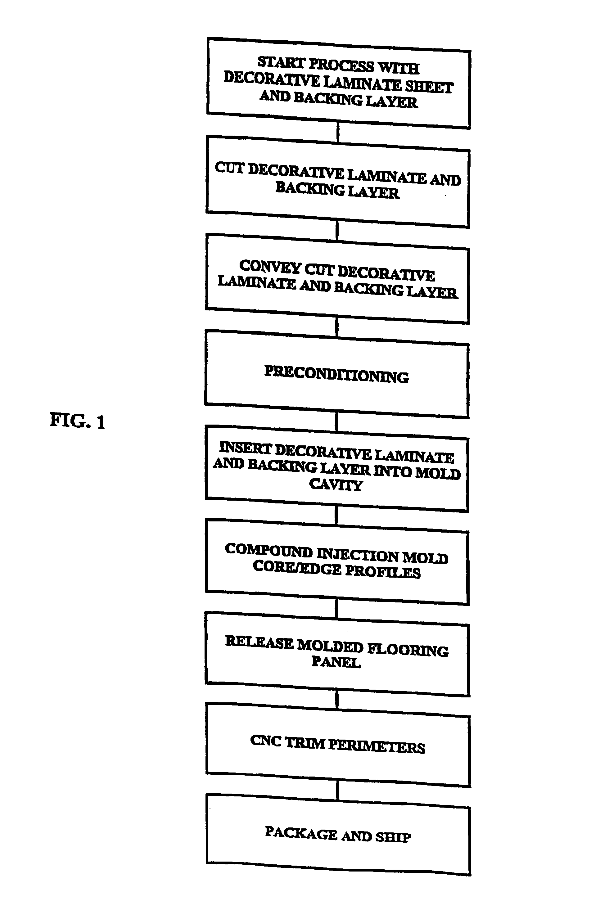
[0037]With reference to FIG. 1, a flow chart of a preferred method in accordance with the present invention is disclosed. The method generally relates to the manufacture of decorative laminate panels, and particularly, the manufacture of decorative laminate flooring planks. The present method provides for the compound injection molding of decorative laminate flooring planks in a piecewise manner. This eliminates the problems associated with conventional line techniques employed in the prior art and discussed above in the “Background of the Invention”.

[0038]The ter...


PUM

PropertyMeasurementUnit
timeaaaaaaaaaa
sizeaaaaaaaaaa
speedaaaaaaaaaa

Abstract

The invention relates to a method for fabricating a decorative laminate panel, wherein the decorative laminate panel includes a decorative laminate layer and a core. The method is achieved by forming a decorative laminate of a predetermined size, placing the decorative laminate within a die cavity, injection molding the core within the die cavity while the decorative laminate remains within the die cavity to form a decorative laminate panel and releasing the formed decorative laminate panel from the die cavity. The invention further relates to a decorative laminate panel manufactured in accordance with the method defined above and a unitary edge profile member adapted for use in the fabrication of a compound injection molded decorative laminate panel.

Description

CROSS REFERENCE TO RELATED APPLICATION[0001]This application is a divisional of U.S. patent application Ser. No. 09 / 797,972, entitled “Compound Injection Molded High Pressure Laminate Flooring”, filed Mar. 5, 2001, now U.S. Pat. No. 6,607,627.BACKGROUND OF THE INVENTION[0002]1. Field of the Invention[0003]The invention relates to a method for the manufacture of decorative laminate panels. More particularly, the invention relates to a method for compound injection molding decorative laminate flooring planks and planks manufactured in accordance with the present method.[0004]2. Description of the Prior Art[0005]Decorative laminate panels, and particularly, decorative laminate flooring planks, are commonly manufactured in a linear manner. That is, the various components move through an extensive processing line where the various components are bound, cut, sized, shaped, boxed and shipped.[0006]The first step in the linear manufacture of decorative laminate flooring is combining the com...

Claims


Application Information

Patent Timeline
Patent Type & Authority Patents(United States)
IPC IPC(8): B29C45/14E04F15/02B44C5/04
CPCB29C45/14467B29C45/14688B44C5/04E04F15/02B29C2045/14532Y10T428/24802Y10T428/183Y10T428/19Y10T428/24736Y10T428/24777Y10T428/163Y10T428/1352
Inventor NELSON, THOMAS J.
Owner PREMARK RWP HLDG
Why Eureka
Try Eureka