
Low thermal mass heated fuser

a low thermal mass, fuser technology, applied in the field of fusers, can solve the problems of requiring substantial time and energy, requiring substantial heating time, and requiring substantial energy consumption,

Inactive Publication Date: 2005-05-24
HEWLETT PACKARD DEV CO LP
View PDF12 Cites 36 Cited by
  • Summary
  • Abstract
  • Description
  • Claims
  • Application Information

AI Technical Summary

Problems solved by technology

Since the roller constitutes a significant thermal mass, it requires substantial time and energy to raise the temperature of the roller to an acceptable operating range.
Hence, these techniques cannot be easily incorporated into the more common fuser roller designs.
Further, in contrast, conventional internal heating of a fuser roller takes substantial warm-up time and associated energy requirements.

Method used


Image

  • Low thermal mass heated fuser
  • Low thermal mass heated fuser
  • Low thermal mass heated fuser

Examples


Embodiment Construction

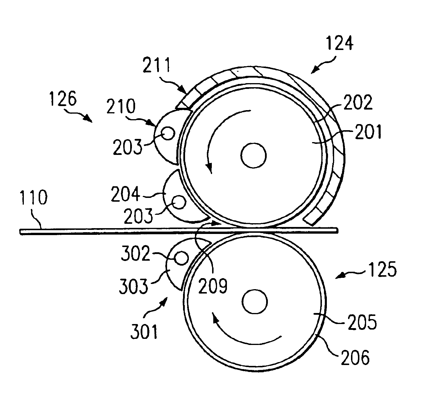
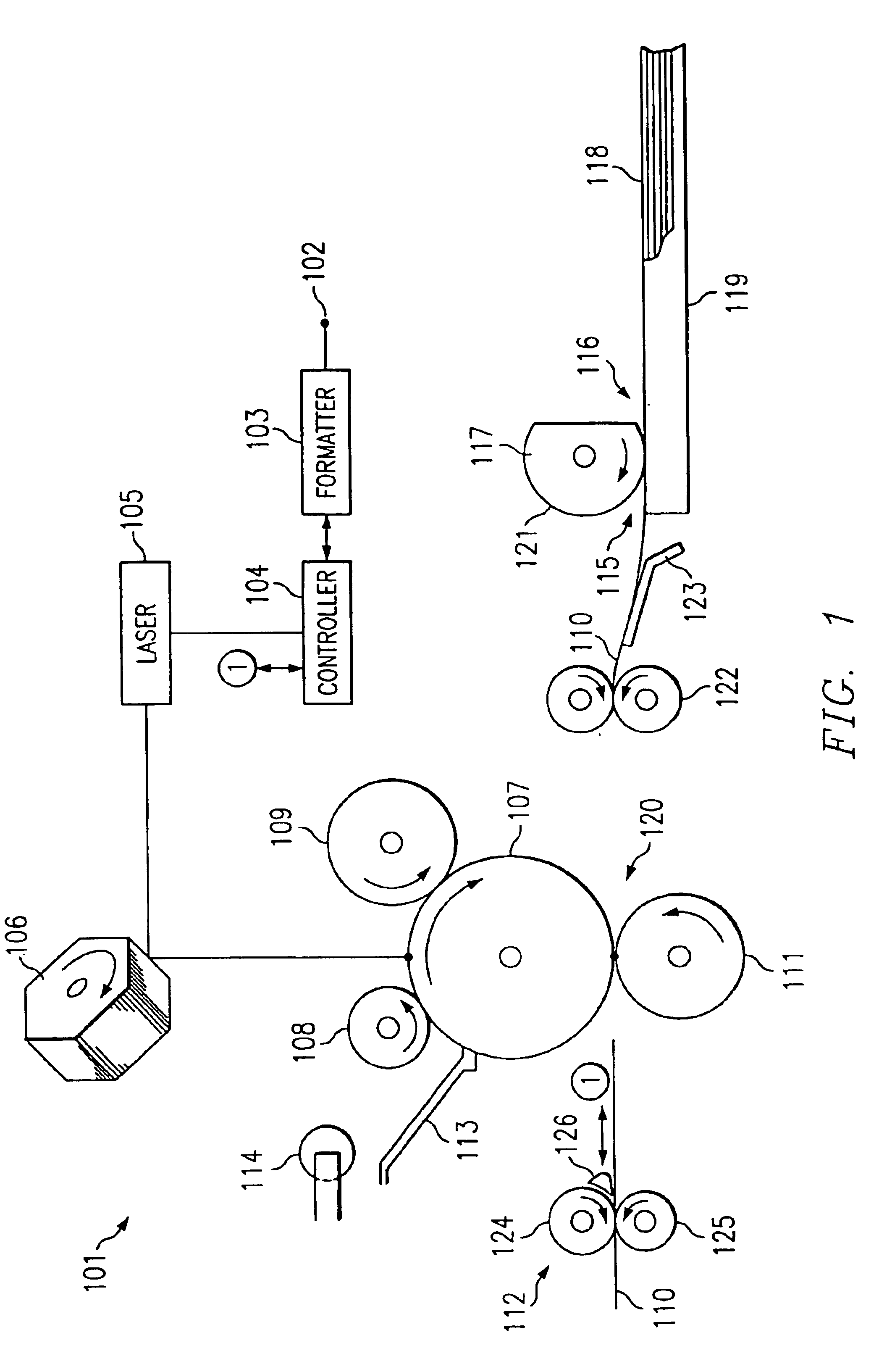
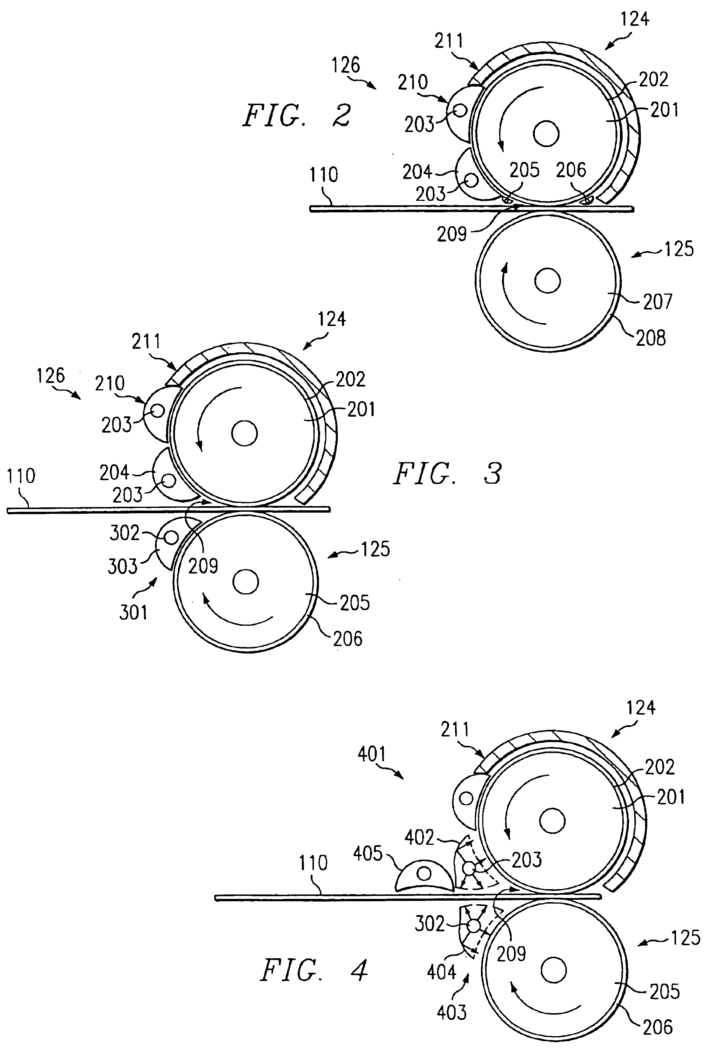
[0015]The present invention is directed to a heated fuser roller that has a low thermal mass outer heating layer supported by a thermally isolating inner core. A radiant heating element is positioned adjacent the roller, near a contact region with a media to be fused. The heating element radiantly heats the outer layer of the fuser roller. The fuser roller includes an elongated cylinder having a core of thermally isolating material and an outer layer of a low thermal mass such as a very thin sheet of metal or metallic coating. The heating element may be a quartz lamp. Temperature sensors may be positioned in contact with or near the roller to detect roller temperature. Operating temperature may be maintained by controlling power supplied to the heating element. In addition to a target temperature value, a controller may receive additional parameters used to calculate a power requirement of the heating element including, for example, toner specific fusing requirements (e.g., heat ene...


PUM


Abstract

A fuser assembly with a roller having a heat absorptive outer layer on an inner core of a thermally isolating material and a radiant heating element positioned adjacent and external to the outer layer of a roller.

Description

TECHNICAL FIELD[0001]The invention relates generally to a fuser for use in an electrophotographic printing device and more particularly, to a radiation heated fuser roller.BACKGROUND OF THE INVENTION[0002]In electrophotographic printing devices, toner particles are used to form the desired image on the print medium, which is usually some type of paper. Once the toner is applied to the paper, the paper is advanced along the paper path to a fuser. In many printers, copiers and other electrophotographic printing devices, the fuser includes a heated fusing roller engaged by a mating pressure roller. As the paper passes between the rollers, toner is fused to the paper through a process of heat and pressure.[0003]A variety of different techniques have been developed to heat the fusing roller. One of the most common techniques for heating a fusing roller uses a quartz lamp placed inside the roller. The lamp is turned on to heat the fusing roller during printing. In this configuration, the ...

Claims


Application Information

Patent Timeline
IPC IPC(8): G03G15/20
CPCG03G15/2053
Inventor BOSS, ROLAND
Owner HEWLETT PACKARD DEV CO LP
Learn More