Installation of flexible lining with flexible collar for lining lateral pipelines

US6899832B2Inactive Publication Date: 2005-05-31INA ACQUISITION

Image

  • Installation of flexible lining with flexible collar for lining lateral pipelines
  • Installation of flexible lining with flexible collar for lining lateral pipelines
  • Installation of flexible lining with flexible collar for lining lateral pipelines

Examples


Embodiment Construction

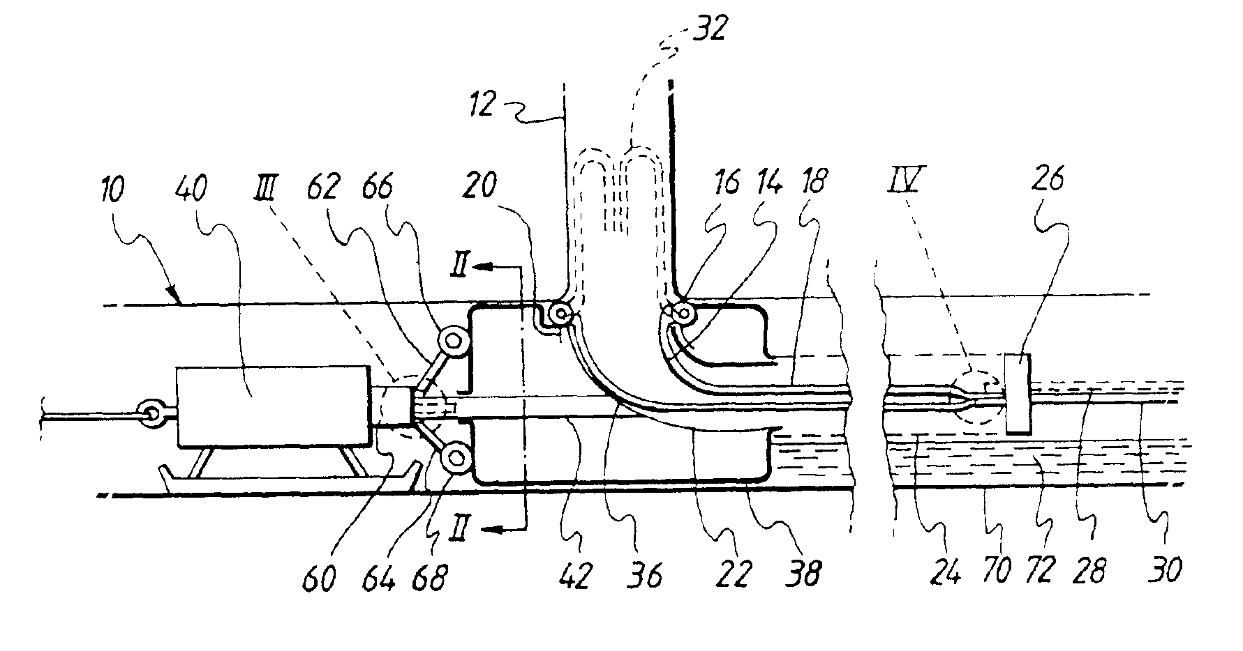
[0017]Referring to the drawings, in FIG. 1 a main line 10 is intersected by a lateral 12 which is to be lined in accordance with a first method of the invention.

[0018]For the lining operation, a resin impregnated flexible lining tube 14 has a beaded end 16 which is reinforced, and forms a ring which seats against the opening of the lateral 12. The tube 14 is loaded inside a carrier tube 18. Carrier tube 18 has one end 20 anchored to an elbow pipe 22, and to the other end of the elbow 22 is connected a containment tube 24. A disc 26 seals the other end of the containment tube, but extending through the disc is a pressure hose 28 and a bleed hose 30.

[0019]The pressure hose 28 and bleed hose 30 can slide through the disc 26 as insertion of the lining tube 14 takes place as will be explained.

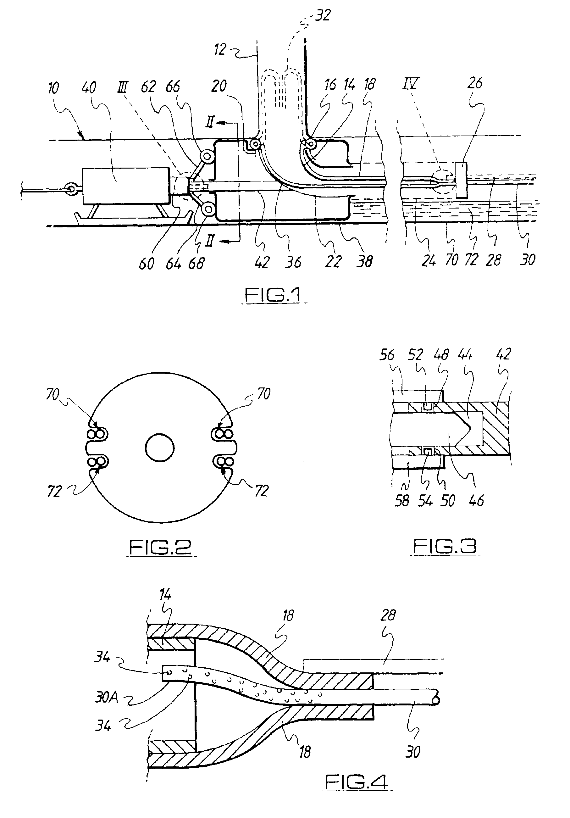
[0020]If reference is made now to FIG. 4, as shown, the tail end of the carrier tube 18 is closed around the bleed hose 30, and the pressure hose 28 is connected to the closed end of the carrier tub...


PUM

PropertyMeasurementUnit
Pressureaaaaaaaaaa
Lengthaaaaaaaaaa

Abstract

A method for installation of a flexible resin impregnable liner for lining a lateral pipe which leads into a main pipe having at one end a flexible collar for installation at the location where the lateral liner meets the main, wherein after installation the collar extends along the interior of the main seating against the opening of the lateral. The flexible liner is installed by inserting the liner into the lateral pipe and using fluid under pressure to expand the lining against the lateral wall to form seals with the collar at the lateral / main pipe junction.

Description

[0001]This is a continuation of application Ser. No. 08 / 941,605, filed Sep. 30, 1997 now U.S. Pat. No. 6,337,114 for INSTALLATION OF FLEXIBLE LINING WITH FLEXIBLE COLLAR FOR LINING LATERAL PIPELINES (as amended) which is a divisional of application Ser. No. 08 / 599,045 filed Feb. 9, 1996 for APPARATUS FOR INSTALLATION OF LINING WITH SEALING COLLAR (as amended), now U.S. Pat. No. 5,975,878 issued on Nov. 2, 1999 which is a divisional of Ser. No. 08 / 394,622, filed Feb. 27, 1995 for INSTALLATION OF LATERAL LININGS WITH SEALING COLLAR FROM THE MAIN PIPELINE OUT (as amended), now U.S. Pat. No. 5,624,629 issued on Apr. 29, 1997, which is a continuation of Ser. No. 07 / 934,678, filed Sep. 10, 1992 for LINING OF PIPELINES OR WAYS now U.S. Pat. No. 5,393,481 issued on Feb. 28, 1995 which is a 371 of PCT / GB91 / 00628 filed Apr. 22, 1991.BACKGROUND OF THE INVENTION[0002]This invention relates to the lining of pipelines or passageways, using flexible tubular materials which are impregnated with cur...

Claims


Application Information

Patent Timeline
31 May 2005
Publication
US6899832B2
IPC
F16L55/16; F16L55/165; F16L55/26; F16L55/179; F16L55/162; B29C63/26; B29C63/36
CPC
F16L55/1651; F16L55/265; F16L55/179; B29C63/36; Y10T428/139; Y10T428/1393
Inventors
WOOD, ERIC