Image processing system capable of applying good texture such as blur

a processing system and texture technology, applied in the field of image processing system capable of applying a good texture, can solve the problems of not being able to achieve sharp images from unable to apply any good texture to images with a long focal length,

Inactive Publication Date: 2005-05-31
OLYMPUS CORP
View PDF13 Cites 159 Cited by
  • Summary
  • Abstract
  • Description
  • Claims
  • Application Information

AI Technical Summary

Problems solved by technology

On the other hand, with the digital camera one can only take a similar image regardless of who the photographer is.
Hence, the above-described methods cannot apply any good texture to an image having a long focal length by a future micro-digital camera.
However, the actual image is blurred, so no sharp image can be obtained from this image by a low-pass filter.
When the camera uses a zoom lens, it is difficult to always supply information about any one of the F-number, f-number, and focal point position.
Such information depends on the system or camera in use, and cannot be generalized and hardly attains compatibility.
An image is blurred selectively using a low-pass filter and high-pass filter, so no good texture can be obtained.
The camera information is not compatible and general, and the blur does not give a good texture.
Unless these problems are solved, the texture of the digital camera is practically difficult to improve.

Method used


Image

  • Image processing system capable of applying good texture such as blur
  • Image processing system capable of applying good texture such as blur
  • Image processing system capable of applying good texture such as blur

Examples


first embodiment

[0101]The first embodiment of the present invention is shown in FIGS. 1 to 5.

[0102]The principle of the present invention will be explained by exemplifying the first embodiment.

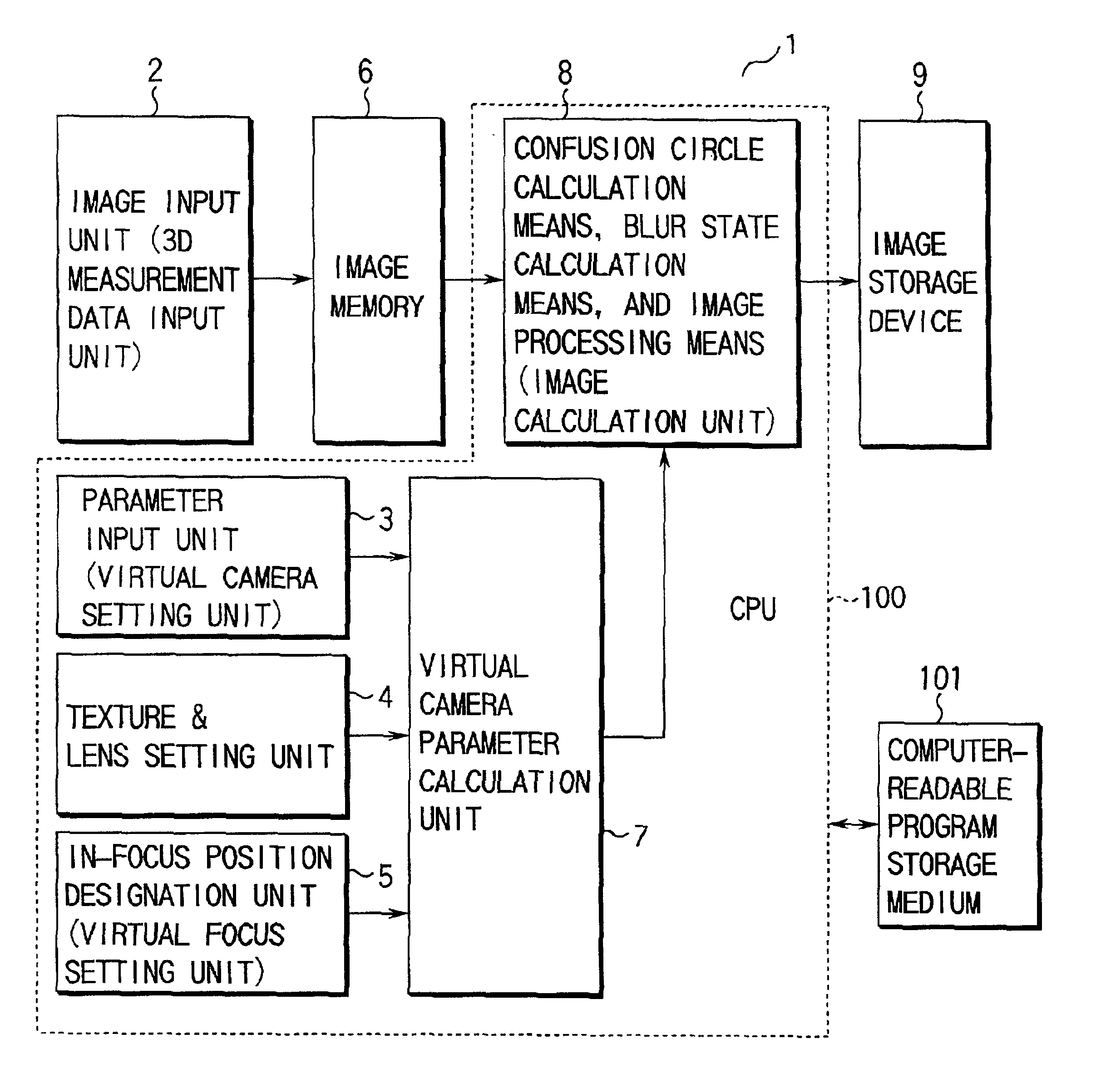
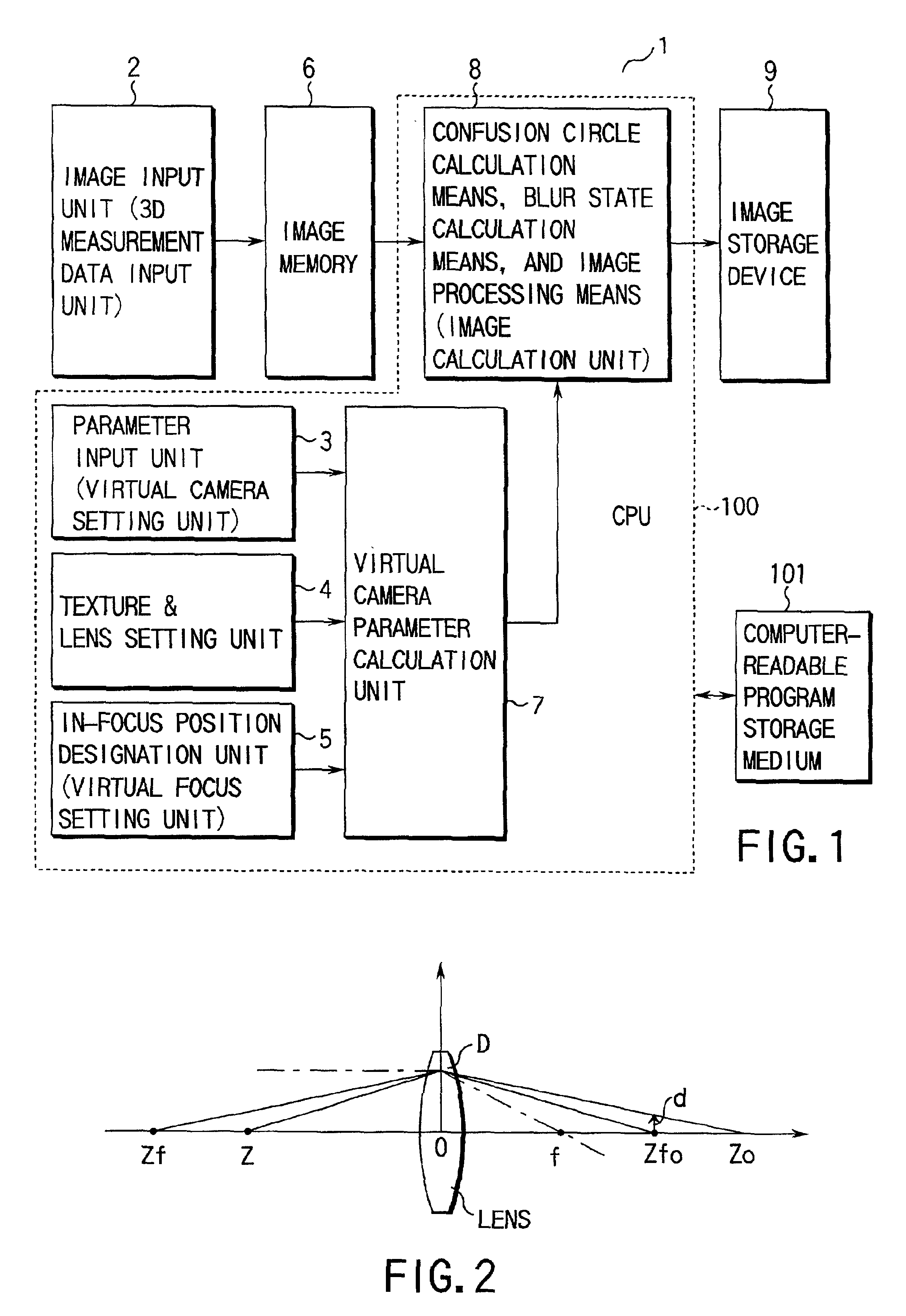
[0103]FIG. 1 shows an arrangement as the functional block of a CPU 100 in order to explain the arrangement of the basic technique of the present invention.

[0104]This function may be implemented by either software or hardware.

[0105]In the software arrangement, respective functional blocks are stored in a computer-readable program storage medium 101 in units of subroutines or object instructions.

[0106]An input / output processing unit 1 in FIG. 1 comprises, as an input unit, processing unit, and output unit for image data and parameters, a three-dimensional (3D) measurement data input unit 2, virtual camera setting unit 3, texture & lens setting unit 4, virtual focus setting unit 5, image memory 6, virtual camera parameter calculation unit 7, image calculation unit 8, image (recording) storage device 9, and the l...

second embodiment

[0280]FIG. 14 shows the second embodiment.

[0281]The basic concept and arrangement method of the second embodiment are the same as in the first embodiment.

[0282]FIG. 14 shows the embodiment for the example of FIG. 12 in which the user interface is enhanced.

[0283]In the first embodiment, the focal point position is set with a volume. In the second embodiment, distance information has already been set in units of pixels. By setting a position to get into focus, the distance from it should be obtained.

[0284]In this embodiment, the F-number is set with a volume, and the focus is adjusted to the head of a person image 31.

[0285]Depth information of the head position is calculated to obtain Z, and a volume position 29 at the lower portion in FIG. 14 automatically moves to determine the focal point position.

[0286]Since distance information in units of pixels includes errors, distances near a designated point may be averaged. The radius or number of pixels subjected to averaging may be separa...

third embodiment

[0288]FIG. 15 shows the third embodiment.

[0289]The basic concept and arrangement method of the third embodiment are the same as in the first embodiment.

[0290]FIG. 15 shows the embodiment in which the user interface is enhanced with a zoom function.

[0291]In the first embodiment, a zoom 32 determines the focal length of the lens. In FIG. 15, the zoom 32 can be set at the upper portion of the window.

[0292]The displayed maximum and minimum focal lengths are set by lens settings.

[0293]By changing the zoom ratio, an image may be enlarged and displayed at the center. Instead, to designate a desired field angle within the entire image, an object image 31 to get into focus is designated with a mouse or the like in FIG. 15.

[0294]The focal point position is determined using the distance to a designated pixel of the object (or the average of several pixels).

[0295]When the zoom ratio is increased, an outer frame 40 within the field angle appears to display the target field angle. In this example...


PUM


Abstract

An image processing apparatus assumes the characteristic of a virtual image sensing optical system, and applies a blur effect corresponding to an in-focus state to a captured image. An image input unit captures image information including distance information to each portion of an object to be photographed. A parameter input unit inputs a parameter from which the effective aperture and focal length of the assumed image sensing optical system can be derived. An in-focal pint position designation unit designates the in-focal pint position of the assumed image sensing optical system. A blur state calculation unit calculates a blur state from the distance information input by the image input unit, the in-focal pint position designated by the in-focal pint position designation unit, and the parameter input by the parameter input unit. An image processing unit applies the blur effect to the image input by the image input unit in correspondence with the blur state calculated by the blur state calculation unit.

Description

BACKGROUND OF THE INVENTION[0001]The present invention relates to an image processing system capable of applying a good texture such as a blur and, more particularly, to an image processing apparatus and method applicable to an advanced-function digital camera serving as a virtual camera, and a computer-readable program storage medium used in the apparatus and method.[0002]With the recent spread and functional advancement of home or personal computers (PCs), personal digital cameras have been developed to take the place of conventional cameras using a silver halide film. Also, higher-grade digital cameras having a CCD of 1,000,000 pixels or more are available.[0003]This high-resolution digital camera is optimal for entertainment purposes: an image can be displayed on a high-resolution display of VGA or higher, or printed by a large-size printer for A4 size or larger.[0004]At the same time, an image processing technique, which has conventionally been used in only special study purpos...

Claims


Application Information

Patent Timeline
Patent Type & Authority Patents(United States)
IPC IPC(8): G06T5/20H04N5/225H04N5/232G06T5/00H04N5/262
CPCG06T5/002H04N5/262
Inventor MIHARA, TAKASHI
Owner OLYMPUS CORP
Why Eureka
Try Eureka