
Disk drive having a head disk assembly enclosure including insert molded components

a disk drive and enclosure technology, applied in the field of disk drives, can solve the problems of increasing the difficulty of achieving the requisite mechanical requirements, the difficulty of fitting disk drives, disk heads, voice coil motors (vcm) plates, etc., and the inability to meet the requirements of mechanical requirements

Inactive Publication Date: 2005-05-31
WESTERN DIGITAL TECH INC
View PDF14 Cites 64 Cited by
  • Summary
  • Abstract
  • Description
  • Claims
  • Application Information

AI Technical Summary

Benefits of technology

The present invention relates to a disk drive with a molded enclosure including a base, a cover, and a coupling mechanism to couple the base to the cover. The molded enclosure is formed by a molding step that includes insert molding a pivot into the base and attaching a second portion of a spindle motor to the first portion to form the spindle motor. The disk drive also includes a head stack assembly with a coil portion that is pivotally coupled to the pivot. The molded enclosure provides improved protection and stability for the disk drive. The method of manufacturing the disk drive includes the molding step and may also include attaching a base voice coil motor plate to the mounting skeleton and molding a cover voice coil motor plate into the cover. The technical effects of the invention include improved protection and stability for the disk drive, simplified manufacturing process, and improved performance of the disk drive.

Problems solved by technology

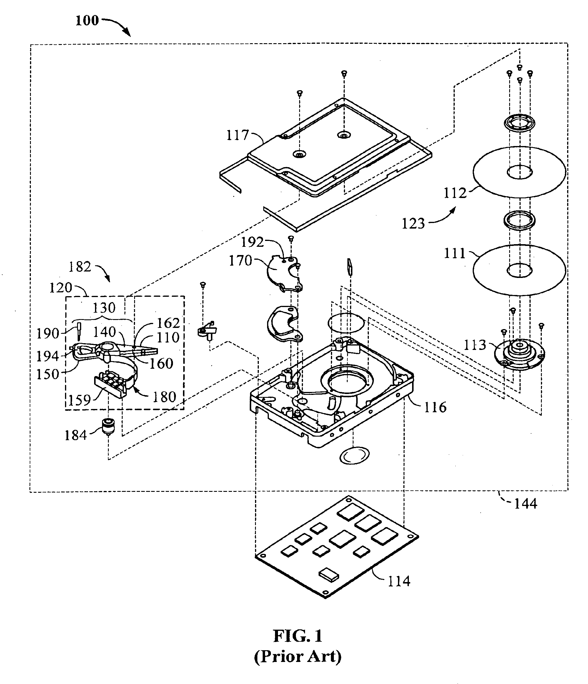
However, with the evolution toward smaller and lower cost disk drives, these traditional methods of manufacture may not be optimal with respect to creating smaller and less expensive disk drives.
As disk drives are designed to fit very small form factors, manufacturing and packaging these small disk drives becomes a very big challenge.
How to fit in the disks, heads, voice coil motor (VCM) plates, motors, actuators, etc., in a stiff enclosure to achieve the requisite mechanical requirements is increasingly difficult.
Further, in addition to the mechanical requirements, electrical components also take up a significant portion of the available volume in a small form factor drive.

Method used


Image

  • Disk drive having a head disk assembly enclosure including insert molded components
  • Disk drive having a head disk assembly enclosure including insert molded components
  • Disk drive having a head disk assembly enclosure including insert molded components

Examples


Embodiment Construction

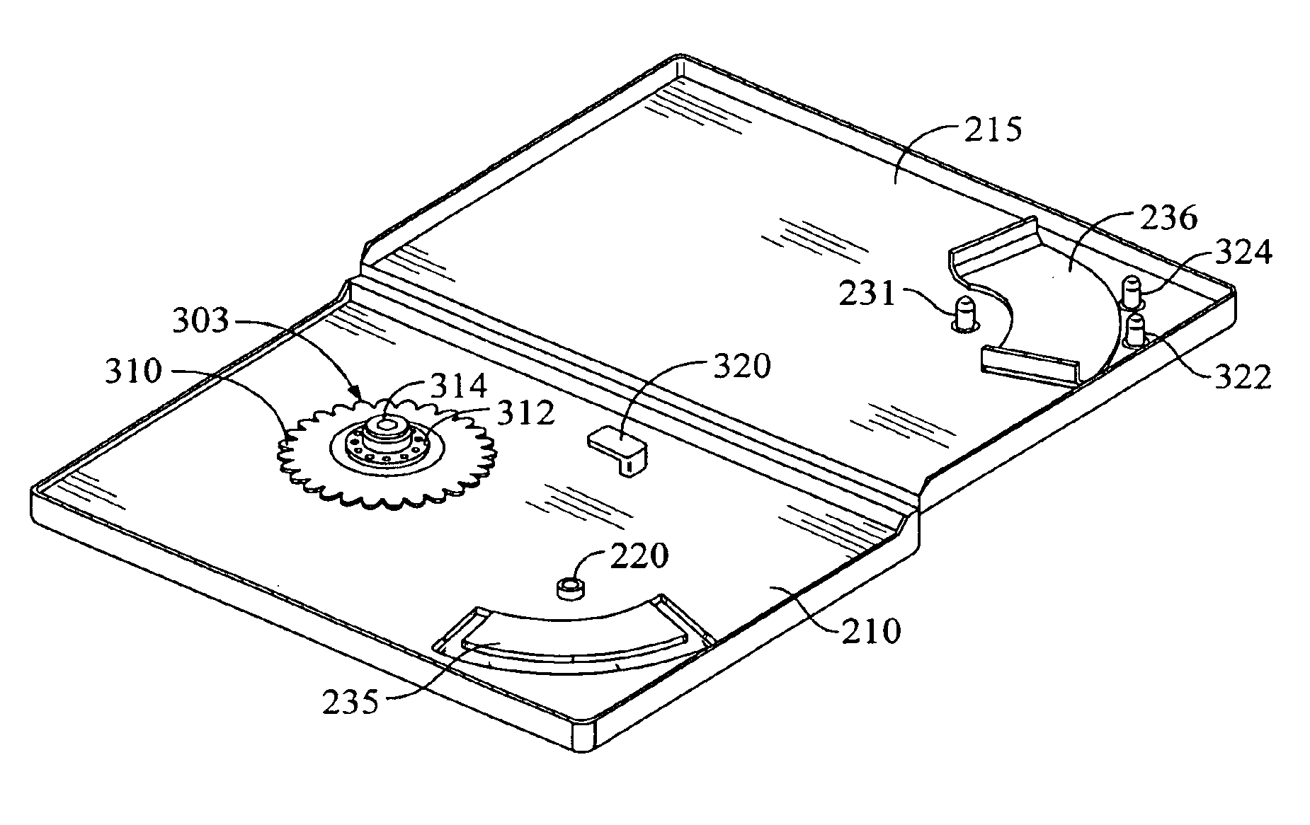
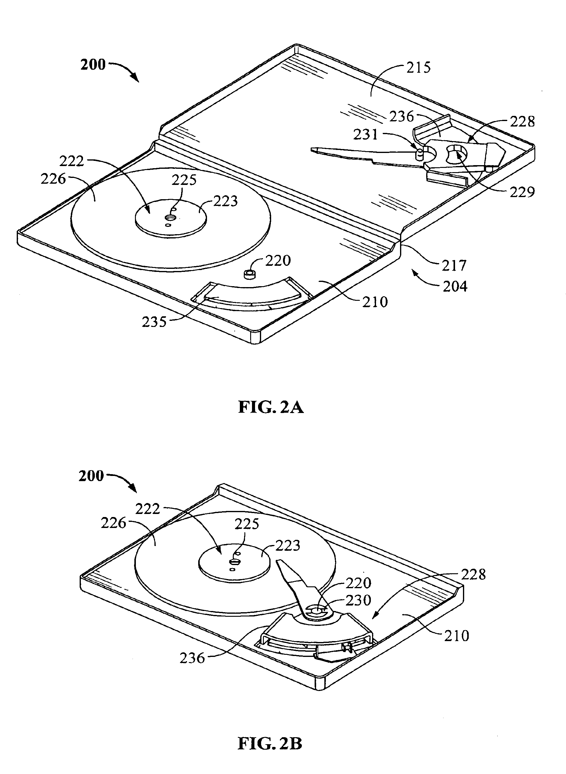
[0033]The present invention relates to a disk drive having a molded head disk assembly enclosure including insert molded components and methods for manufacturing such a disk drive. FIG. 2A is a perspective view of a disk drive 200 having a molded head disk assembly (HDA) enclosure 204 including insert molded components, according to one embodiment of the present invention. FIG. 2B is a perspective view of the disk drive of FIG. 2A shown with all of the components engaged and the cover removed. With reference to FIGS. 2A and 2B collectively, the molded HDA enclosure 204 includes a base 210, a cover 215, and a coupling mechanism, such as a hinge 217, to couple the base 210 to the cover 215. A pivot 220 is insert molded into the base 210. The disk drive 200 also includes a spindle motor 222. The spindle motor 222 may be insert molded into the base 210.

[0034]Also, as will be discussed in more detail later, a first portion of the spindle motor 222 may be insert molded into the base 210. ...


PUM

PropertyMeasurementUnit
metallicaaaaaaaaaa
forceaaaaaaaaaa
load biasing forceaaaaaaaaaa

Abstract

Disclosed is disk drive having a molded head disk assembly enclosure including insert molded components and methods for manufacturing the same. In one aspect, the invention may be regarded as a disk drive having a molded enclosure including a base, a cover, and a coupling mechanism to couple the base to the cover. A pivot is insert molded into the base. A first portion of a spindle motor is insert molded into the base. A second portion of a spindle motor is attached to the first portion to form the spindle motor. Further, a disk is mounted to the spindle motor and a head stack assembly having a coil portion is pivotally coupled to the pivot.

Description

BACKGROUND OF THE INVENTION[0001]1. Field of the Invention[0002]The present invention relates to disk drives. More particularly, the present invention relates to disk drives having a head disk assembly enclosure including insert molded components and methods for manufacturing such disk drives.[0003]2. Description of the Prior Art and Related Information[0004]A typical hard disk drive includes a head disk assembly (“HDA”) and a printed circuit board assembly (“PCBA”). The HDA includes at least one magnetic disk (“disk”), a spindle motor for rotating the disk, and a head stack assembly (“HSA”) that includes a head with at least one transducer for reading and writing data. The HSA is controllably positioned by a servo system in order to read or write information from or to particular tracks on the disk. The typical HSA has three primary portions: (1) an actuator assembly that moves in response to the servo control system; (2) a head gimbal assembly (“HGA”) that extends from the actuato...

Claims


Application Information

Patent Timeline
Patent Type & Authority Patents(United States)
IPC IPC(8): G11B25/04
CPCG11B25/043
Inventor BUTLER, WALTER W.
Owner WESTERN DIGITAL TECH INC
Learn More