Connector lock structure

a technology of connecting parts and locking parts, applied in the direction of electrical equipment, connection, coupling device connection, etc., can solve the problems of fatigue destruction, increase in the size of the connector housing, and reduce the engagement strength of the engaging portion, so as to reduce the outside dimension of the first connector housing and miniaturize the connector

Inactive Publication Date: 2005-06-07
YAZAKI CORP
View PDF8 Cites 20 Cited by
  • Summary
  • Abstract
  • Description
  • Claims
  • Application Information

AI Technical Summary

Benefits of technology

[0028]Thus, the lock structure can suppress the flexible lock member and the operating arm from protruding upwardly from the outer wall surface of the first connector housing. Consequently, the lock structure according to the invention can prevent the outside dimension of the first connector housing from increasing owing to the protrusion of the flexible lock member and the operating arm. Thus, the miniaturization of the connector can be achieved.

Problems solved by technology

Fatigue due to stress concentration in the leg portions 3a and 5a may result in permanent deflections thereof and may cause reduction in an engaging strength of the engaging portion 3c, or fatigue destruction thereof.
Thus, the lock structure of the related lock portion 1 has a problem in that the size of the connector housing increase owing to increase in the dimension of the outside diameter of the connector housing, which is caused by outward protrusion of the engaging portion 3c.

Method used


Image

  • Connector lock structure
  • Connector lock structure
  • Connector lock structure

Examples


Embodiment Construction

[0036]Hereinafter, a connector lock structure according to an embodiment of the invention is described in detail with reference to the accompanying drawings.

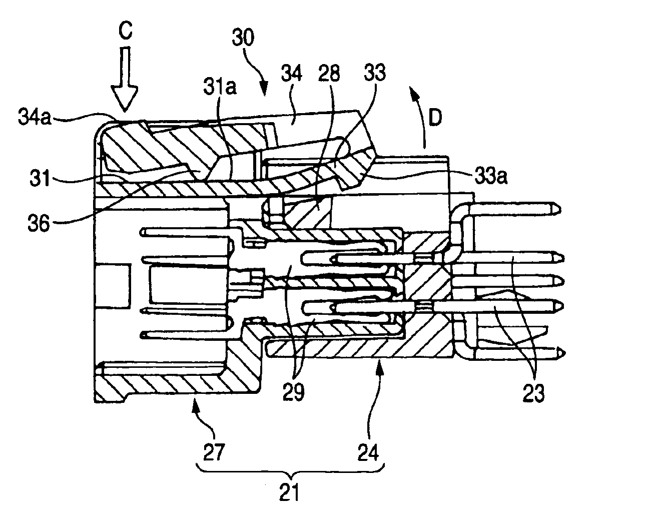
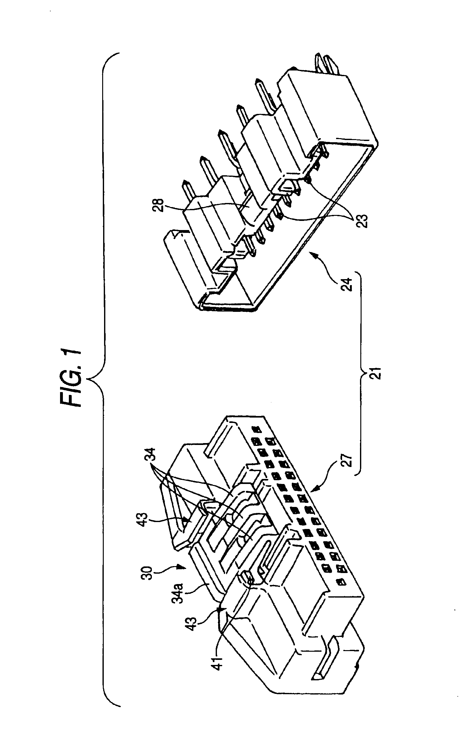
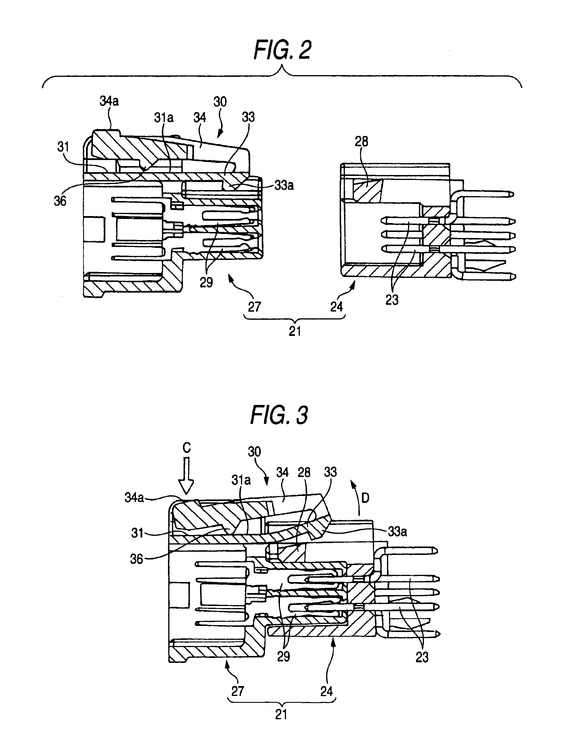
[0037]FIG. 1 is a perspective view illustrating a connector employing a connector lock structure according to an embodiment of the invention. FIG. 2 is a longitudinally sectional view illustrating the connector shown in FIG. 1. FIG. 3 is a longitudinally sectional explanatory view illustrating releasing of the locked condition of the connector shown in FIG. 2. FIG. 4 is a front view illustrating a lock portion shown in FIG. 1.

[0038]As shown in FIGS. 1 and 2, a connector 21 according to this embodiment includes a female connector housing 24, which accommodates and holds a plurality of male terminal metal fittings 23, and also includes a male connector housing 27, which accommodates and holds a plurality of female terminal metal fittings 29.

[0039]When the female connector housing 24 and the male connector housing 27 are fitting-co...


PUM


Abstract

A connector lock structure includes a first connector housing, a second connector housing which is fitted to the first connector housing, a flexible lock member which is frontwardly extended from the first connector housing along a connector fitting direction and which has an engagement portion provided at an end portion thereof, a latch member which is provided on the second connector housing and which is engaged with the engagement portion, an operating arm which upwardly protrudes from the end portion of the lock member and rearwardly extends and which has a operation portion provided at a rear end portion thereof, and a fulcrum projection which is provided on at least one of an outer wall face of the lock member and a bottom surface of the operating arm facing the outer wall face.

Description

BACKGROUND OF THE INVENTION[0001]This invention generally relates to a connector lock structure, and more particularly to a connector lock structure having a mechanism for releasing a locked condition of connector housings.[0002]Hitherto, there has been a lock structure shown in FIGS. 5 and 6 (see, for example, JP-A-2000-150069), which serves as a structure for connecting male and female connector housings to each other, for locking this connected condition, and for releasing this locked condition.[0003]The lock structure shown in FIGS. 5 and 6 is configured so that a lock portion 1 having a lock arm 3 and a releasing arm 5 is formed integrally with the female connector housing.[0004]As shown in FIG. 6, the lock arm 3 includes two curved leg portions 3a formed in such a way as to upwardly protrude and extend from an outer wall 7, two arm portions 3b respectively and horizontally extending from the two leg portions 3a along a connector fitting direction toward a latch portion of a co...

Claims


Application Information

Patent Timeline
Patent Type & Authority Patents(United States)
IPC IPC(8): H01R13/627H01R13/639
CPCH01R13/6272
Inventor MURO, TAKASHIMATSUMURA, KAORUSAKAMOTO, NOBUYUKI
Owner YAZAKI CORP
Why Eureka
Try Eureka