Method and apparatus for automatically eliminating inferred latches

a technology of automatic elimination and latches, applied in the field of hardware description languages, can solve problems such as inferred latches, slowness, and inability to automatically eliminate latches, and achieve the effects of avoiding potential design errors and problems, avoiding inferred latches, and avoiding inferred latches

Active Publication Date: 2005-06-07
XILINX INC
View PDF5 Cites 10 Cited by
  • Summary
  • Abstract
  • Description
  • Claims
  • Application Information

AI Technical Summary

Benefits of technology

This patent describes how to automatically remove certain parts of software designs called latches. It does this by analyzing the structure of the software and identifying specific parts of it that may cause issues. Then, it modifies these parts to fix any problems they might have. Overall, this makes the software faster and easier to develop.

Problems solved by technology

This patent discusses how software languages like HDLs are used to design computer circuits. However, these languages sometimes generate unnecessary signals called inferred latches during the simulation phase. These issues slow down the design process and lead to poor quality designs. Therefore, there is a technical problem of finding a solution to automate the elimination of inferred latches generated by HDL codes.

Method used


Image

  • Method and apparatus for automatically eliminating inferred latches
  • Method and apparatus for automatically eliminating inferred latches
  • Method and apparatus for automatically eliminating inferred latches

Examples


case i

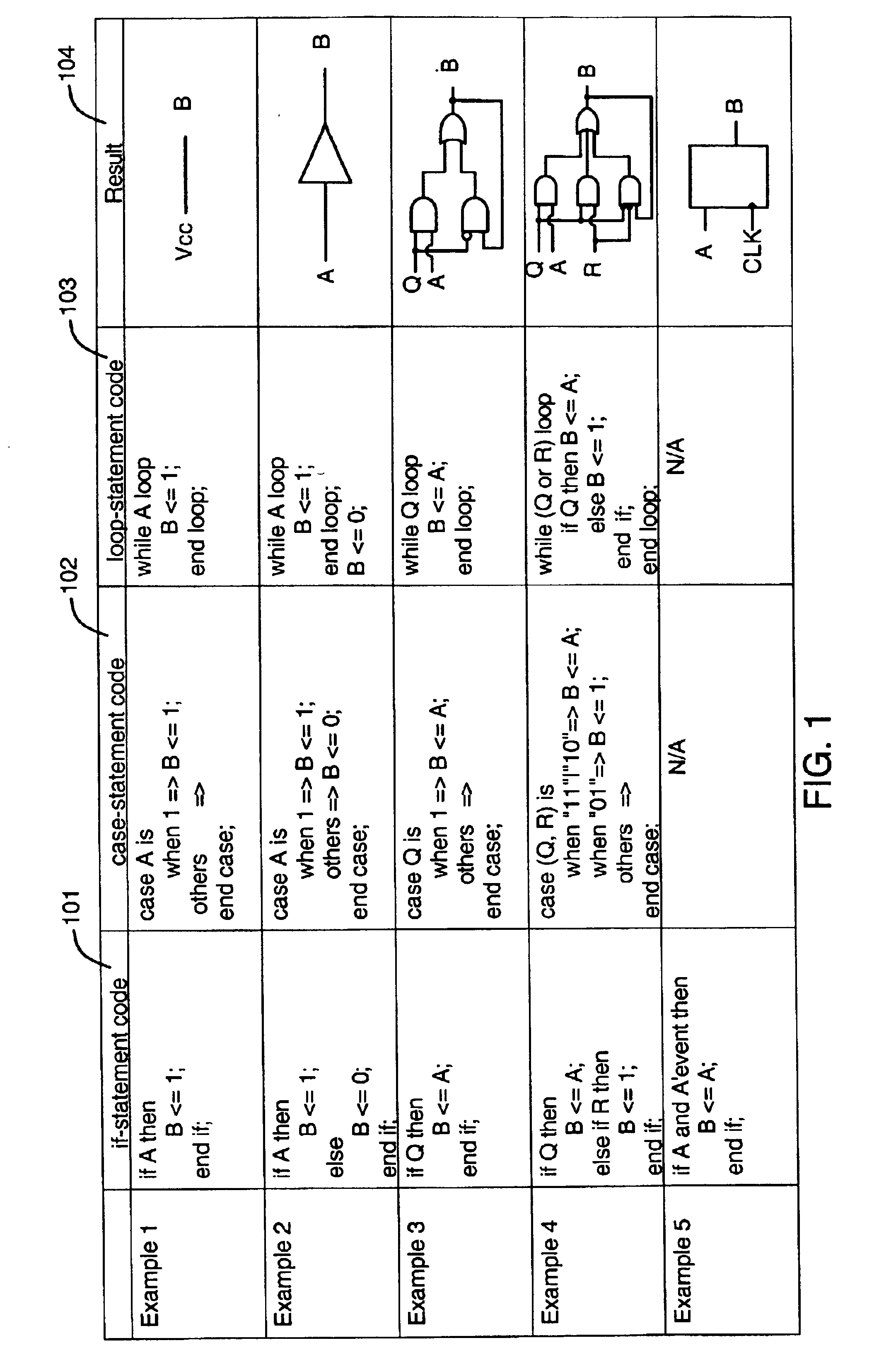
[0066]In another example, HDL code having multi-level conditional logic is as follows:[0067]if (J) then[0068]case I is[0069]when “00”=>A [0070]when “01”=>A [0071]when “10”=>[0072]when others =>A [0073]end case;[0074]B [0075]end if;

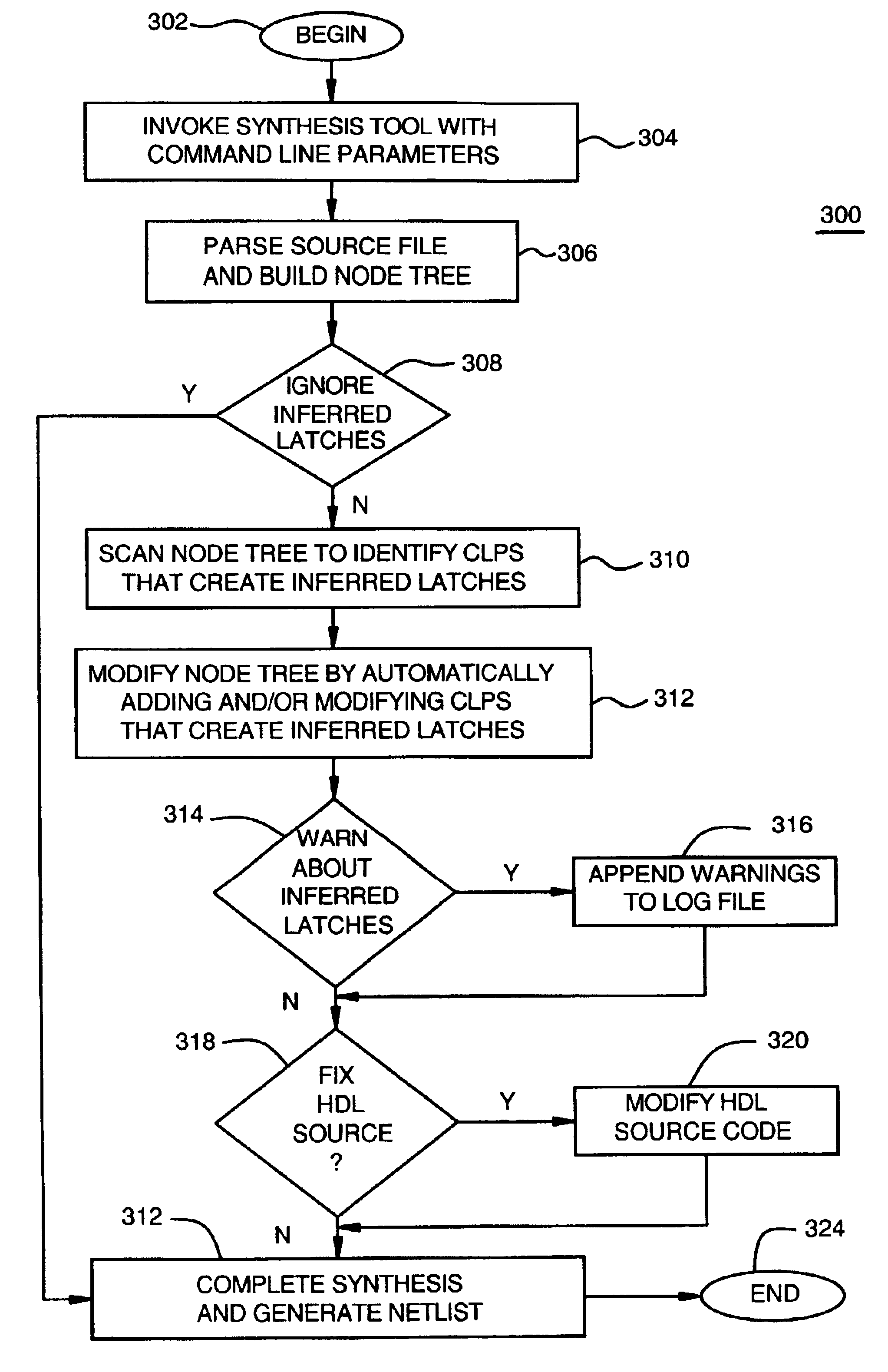
The lowest level CLP is found, which is the case-statement. It is determined that for the condition I=“10”, signal A is not assigned. A default assignment is determined, and revises internal nodes of a resulting node tree to include the default assignment.

[0076]A next CLP is identified, which is an if-statement in this example. Assigned variables (“targets”) are identified as signals A and B. Since the if-statement does not have an “else” section, an “else” section is added. Signals A and B are assigned default values in the added else section. If the HDL code is to be modified, the resulting code is as follows:[0077]if (J) then[0078]case I is[0079]when “00”=>A [0080]when “01”=>A [0081]when “10”=>A [0082]when others =>A [0083]end case;[0084]B [0085]else[00...


PUM


Abstract

Method and apparatus for automatically eliminating inferred latches created by hardware design language (HDL) source code is described. A node tree is built from the HDL source code based on the HDL's Language Reference Manual. The node tree is scanned to identify one or more conditional logic constructs that are sources for creation of inferred latches. A modified node tree is generated by automatically adding and/or modifying sub-productions of the conditional language constructs that create the inferred latches.

Description


Claims


Application Information

Patent Timeline
Owner XILINX INC
Why Eureka
Try Eureka