[0024]This invention uses most of the objects of patent application 12363738 and also exhibits most of the advantages of that invention.
[0025]The objects and advantages that are more specific to this invention are:
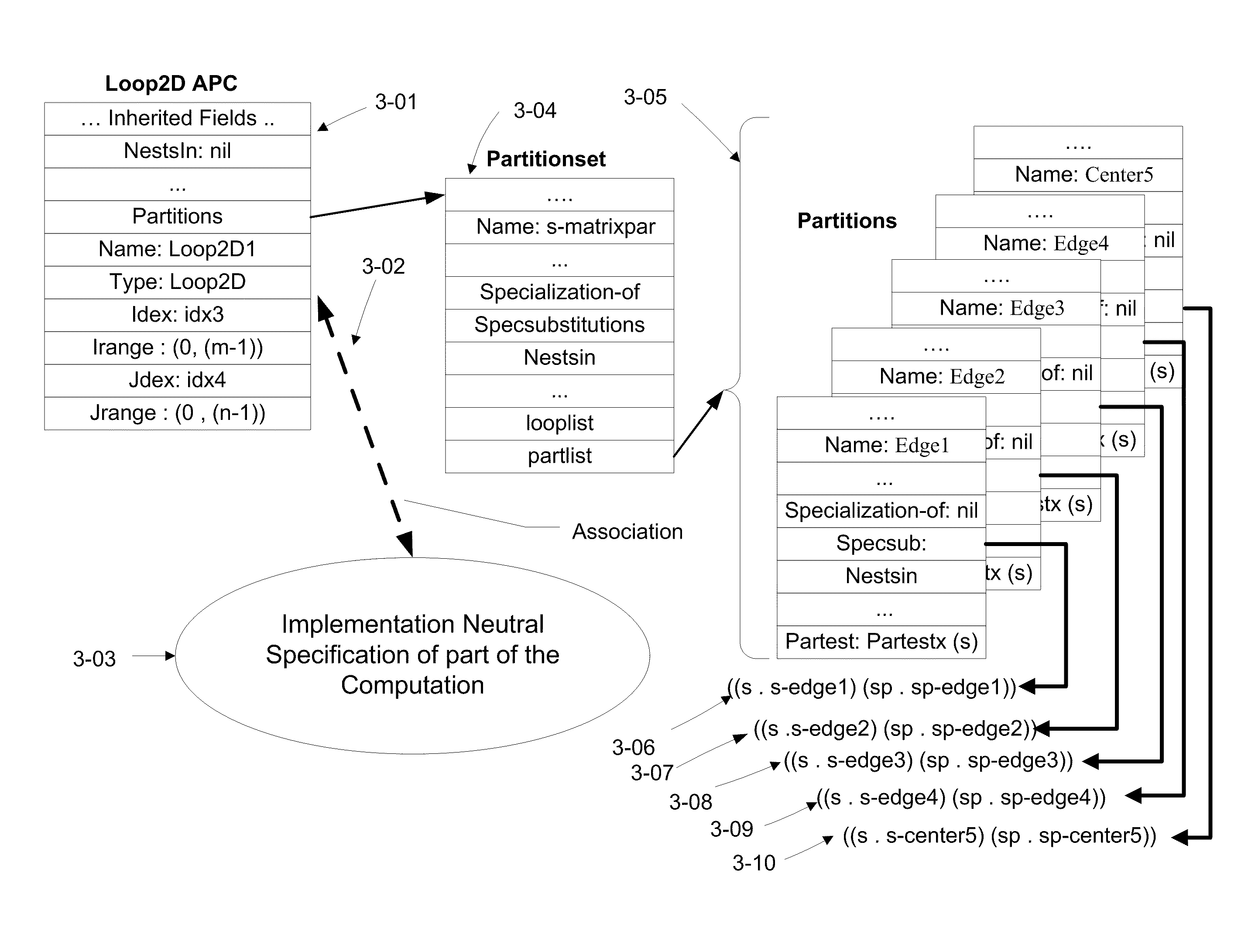
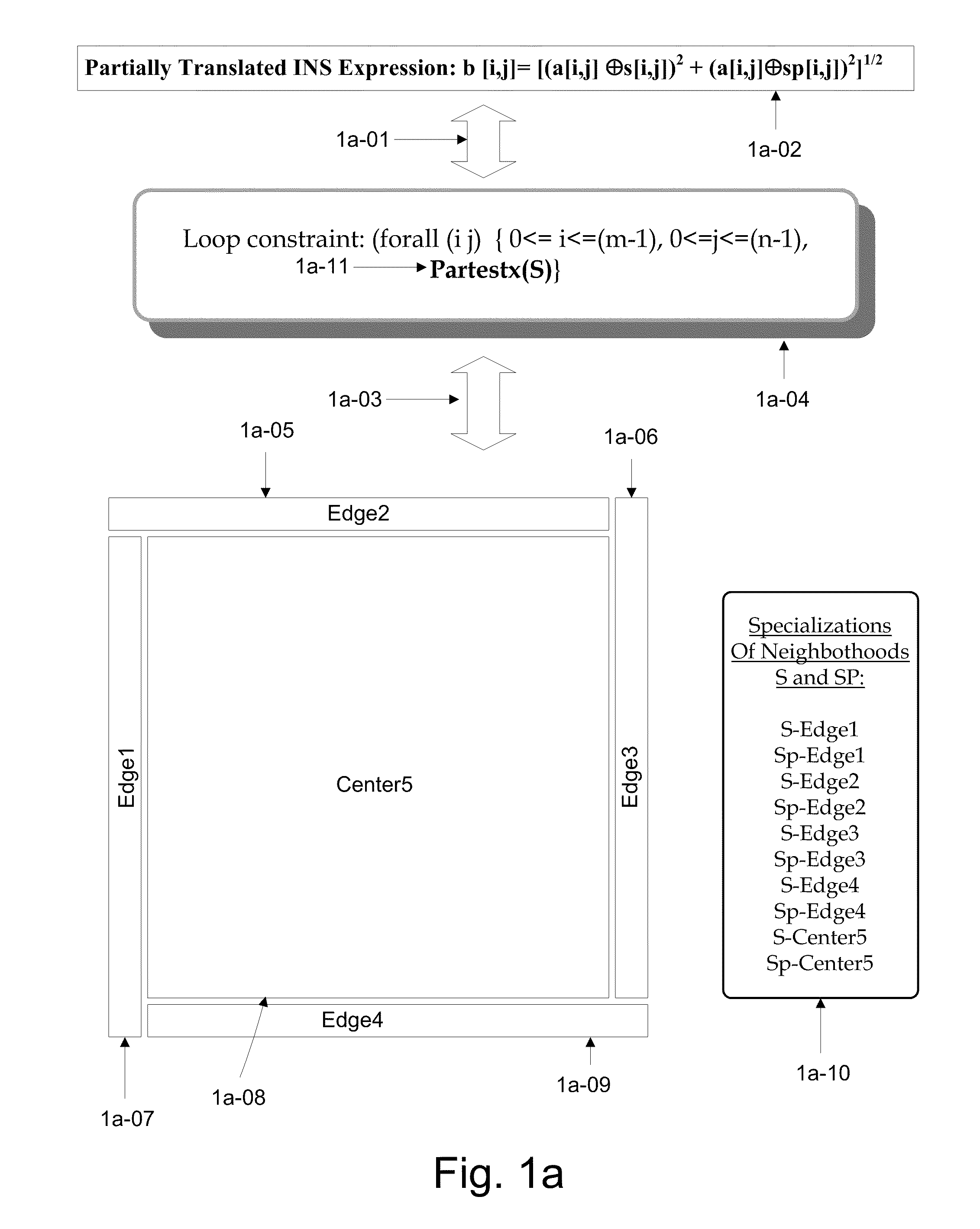
[0026]Synthetic Partitions: Natural partitions express the logical case structure of a specific computation. For example, because of the natural case structure of a specific computation, an image pattern detection algorithm may choose to compute edge pixels differently and possibly separately from non-edge pixels in an image. So, such an algorithm would be naturally partitioned into edges and non-edges (i.e., the center). Similarly, an image averaging computation that averages a pixel with all of its contiguous neighboring pixels will need to compute the image corner pixels differently from the edge pixels differently from the non-corner, non-edge pixels because each case averages over a differing number of pixels (e.g., corners average over four pixels, non-corner edges over six pixels and non-corners, non-edges over nine pixels). While natural partitions express the natural case structure of a computation, they do not say much about the design of a target implementation form and therefore, for example, do not do the job of specifying load leveling of the computation over a set of processors. But that level of specification is not really part of their job since this invention factors classes of implementational features into separate sets so that they can be dealt with separately.
[0027]However synthetic partitions provide the machinery to take the next step in developing an implementation by introducing additional constraints on the desired implementation. Synthetic partitions are constructed to introduce some design features but not all design features of the final implementation form. In fact, they eschew (to a degree) specifying purely GPL level structures and features because that would introduce so much combinatorial and inter-relational complexity, that the solution space would explode preventing easy solutions and likely as not, preventing most acceptable solutions. Rather, synthetic partitions allow the programming process to be decomposed into stages; one stage that decides which partitions that can be run in parallel and which are best run serially. This first stage is followed by is one or more later stages that map the results of the first stage into the code structures that will be needed to implement the synthetic partition constraints in a programming language. For example, synthetic partitions may be constructed to allow the computational load to be balanced among processors without specifying the plethora of coding details necessary to fully implement that constraint. Thus, a synthetic partition implies something about the organization and structure of the developing target program but defers the actual expression of that organization and structure until later because that implied organization and structure is provisional. It may change because of other design features that must also be included in the final implementation (e.g., a particular thread protocol may affect how that organization and structure are mapped into a particular GPL on a particular execution platform). A synthetic partition does not determine the target program in detail but rather constrains elements of it, e.g., it might require the target program to have some code to split up loops into pieces that can potentially be run in parallel (e.g., the loop over the non-edge portion of an image might slice the non-edge portion into pieces that can potentially be run in parallel). Further, a synthetic partition might imply that separate pieces (e.g., image edges) should be grouped together and run sequentially in a single thread. Moreover, a synthetic partition (in conjunction with execution platform specification knowledge and knowledge of the properties of the specific computation) might constraint the pattern of synchronization among implied parallel computational parts to adhere to some overall synchronization design pattern. For example, if the nature of the computation allows the loops to be decomposed into independent computational parts, then the implied synchronization design might consist of a controller routine that initiates each parallel thread using a set of thread routines for each thread. Each such thread routine would notify the controller routine is when it is complete. After initiating all thread routines, the controller routine might have a synchronization construct that waits until all threads are complete. Variations on that design might include some error code that times out if any thread fails to complete in some reasonable time.
[0028]The advantage of synthetic partitions is that they allow a design feature (e.g., the slicing of an image center in order to load level a computation) to be provisionally expressed without immediately casting it into a GPL or near GPL form where further design, change and manipulation would be difficult. This mechanism defers making low level design decisions until the broad architectural features are decided and integrated. Furthermore, a design feature like slicing can be combined with other related design features at a conceptual or problem domain level thereby conceptually or provisionally altering the implied GPL design without immediately trying to build in each design feature in a GPL form. For example, a partitioning design feature can be combined with an Instruction Level Parallelism design feature and subsequently, both of these can be later combined with computational load leveling and threading design features.
[0029]This style of doing business allows the generator to have a library of frameworks (i.e., GPL like shells) each of which represents some reasonably small combination of related design features. Additionally, each such framework has a set of holes that are tailored to the combination of broad architectural features and designed to receive computational payloads (e.g., partitions of a particular domain specific type). For example a particular framework might be designed to receive partitions such as image edges that are “probably” order n computations (i.e., lightweight computations) or alternatively, to receive partitions such as image centers that are “probably” order n squared computations (i.e., heavyweight computations). Such a framework might introduce a set of cooperating GPL routines, the parametric plumbing between those routines as well as holes that define the details of the input and output plumbing that connects the data items specific to the implementation neutral specification of the computation. There may be further GPL design features such as synchronization and thread control. But the framework says nothing about exactly what kind of a computation is occurring it holes. That will be supplied by the computational payload defined in the logical architecture.


