
Vapor vent valve for fuel pump module

a technology of vapor vent valve and fuel pump, which is applied in the direction of valve operating means/release devices, functional valve types, machines/engines, etc., can solve problems such as unsatisfactory emissions, and achieve the effect of reducing fuel vapor emissions

Inactive Publication Date: 2005-06-14
DENSO INTERNATIONAL AMERICA +1
View PDF8 Cites 7 Cited by
  • Summary
  • Abstract
  • Description
  • Claims
  • Application Information

AI Technical Summary

Benefits of technology

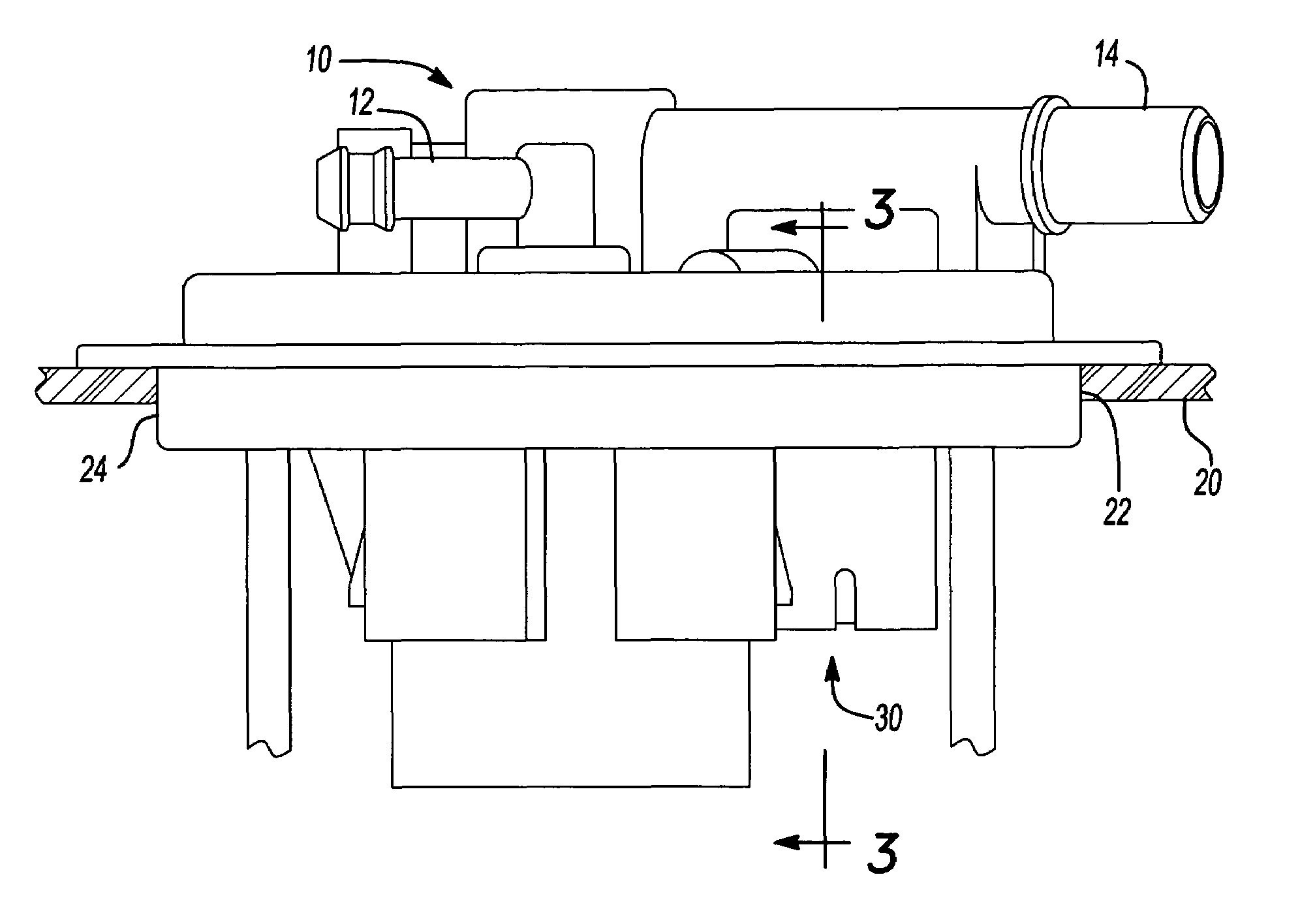
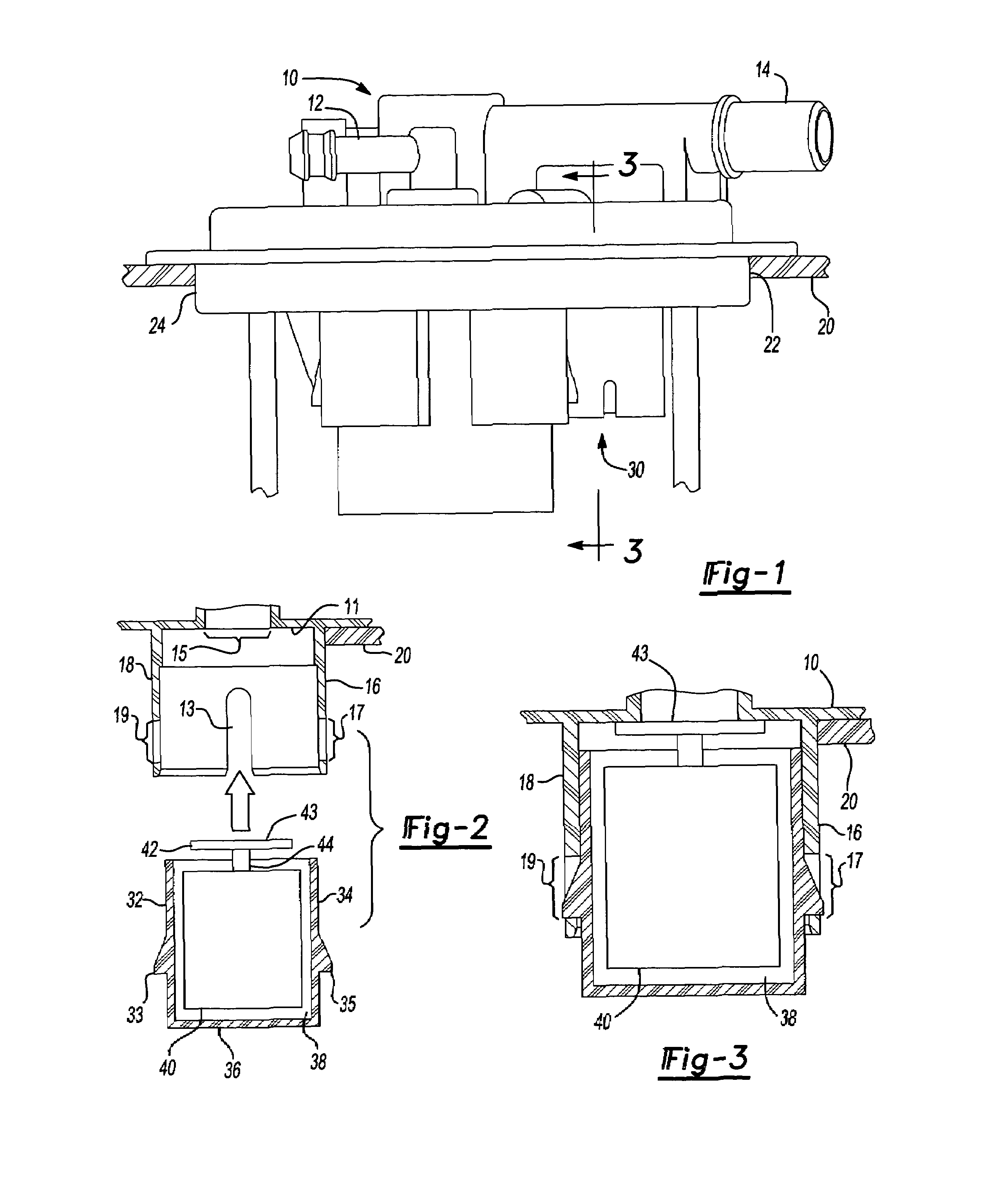
The present invention aims to reduce fuel vapor emissions from a fuel tank ventilation system by providing a fuel pump modular flange with one or more vapor valves directly incorporated within. This eliminates the need for additional holes through the fuel tank. The invention also provides a means for reducing permeation emissions of fuel vapor by eliminating an unnecessary sealing point between a vent valve housing and a fuel pump module flange. The vent valve assembly operates directly against the fuel pump modular flange, preventing fuel / vapor from bypassing the valve housing. The design reduces complication, lowers cost, and improves quality by the reduction in potential leakage paths.

Problems solved by technology

Unfortunately there is the potential that vapor or fuel may still bypass the valve housing and O-ring seal either through a faulty seal or permeation, even when the valve is in the closed position, creating undesired emissions.

Method used


Image

  • Vapor vent valve for fuel pump module
  • Vapor vent valve for fuel pump module

Examples


Embodiment Construction

[0015]The following description of the preferred embodiment(s) is merely exemplary in nature and is in no way intended to limit the invention, its application, or uses.

[0016]Fuel pump modules operate as a means for delivering fuel stored within a fuel tank to the fuel lines for combustion by the engine. They generally embody a pump element attached to a flange for mounting the module through an aperture in the fuel tank wall. The flange seals off the interior volume of the fuel tank to prevent spillage of the fuel stored within. As the fuel is spent, fuel vapor builds up within the fuel tank and must be vented to a specific location outside of the fuel tank to prevent vapor-lock. It has become advantageous to incorporate a vapor vent valve within the modular flange, providing the means of venting the fuel vapors while eliminating the need for an additional aperture through the tank wall, and additionally, another potential source for emissions. Thus, it is the primary object of the ...


PUM


Abstract

A vapor vent valve for a fuel pump module, wherein the valve assembly attaches directly to the bottom side of the fuel pump module flange within the interior volume of the fuel tank. When rising fuel exerts a force on the valve assembly pushing the float assembly upwards, the valve head attached to the float assembly seals directly against a valve seat on the underside of the modular flange, covering the vapor release aperture located through the flange, preventing fuel from escaping through the vent aperture. In providing a direct seal of the valve head against the modular flange, additional sealing means and potential emission sources between the valve housing and the modular flange are eliminated.

Description

FIELD OF THE INVENTION[0001]The present invention relates to low-emission fuel vapor venting systems. Specifically, the invention relates to minimizing potential emission by incorporating a vapor vent valve in the fuel pump modular flange.BACKGROUND OF THE INVENTION[0002]Controlling fuel vapor in vehicle fuel tanks has long been an objective for automobile manufacturers and suppliers of fuel systems components. Fuel vapor can be created in the fuel tank by temperature differences between the fuel tank and liquid fuel from a fuel pump, as well as by sloshing and agitation of the fuel tank during normal vehicle operation. The fuel vapor collects in the space above the fuel within the tank and is normally released through one or more vent valves located within the wall of the fuel tank. This prevents pressurization of the tank or the creation of a vacuum therewithin as a result of fluctuations in fuel volume due to changes in temperature, atmospheric pressure, or the drop in fuel level...

Claims


Application Information

Patent Timeline
Patent Type & Authority Patents(United States)
IPC IPC(8): B60K15/035B60K15/03F16K24/04F16K24/00F02M25/08F02M37/00F16K31/22
CPCF16K24/044Y10T137/86324Y10T137/3099
Inventor POWELL, PATRICKNAGASE, TAKEHIROTAKAHASHI, TETSUYA
Owner DENSO INTERNATIONAL AMERICA
Learn More