Vehicle capless refueling system

a technology of refueling system and vehicle, which is applied in the direction of vehicle components, transportation and packaging, propulsion parts, etc., can solve the problems of degrading fuel quality, affecting the service life of the vehicle, so as to reduce the over-pressure of the underground fuel storage tank, reduce the amount of fuel consumed, and reduce the effect of fuel emissions

Active Publication Date: 2018-02-15
FORD GLOBAL TECH LLC
View PDF12 Cites 2 Cited by
  • Summary
  • Abstract
  • Description
  • Claims
  • Application Information

AI Technical Summary

Benefits of technology

[0002]Fuel systems for engines, e.g., diesel or gasoline engines, may include capless fuel port on a fuel filler pipe coupled to a fuel tank for replenishing fuel in the tank. Such a capless fueling port may include a fuel valve or sealing door which remains closed to seal off fuel system and reduce fuel vapor emissions from the fuel tank to the external atmosphere. The fuel valve or sealing door on the capless fuel port may be opened by inserting a fuel nozzle into the fuel port during refueling. Furthermore, the capless fueling port may be designed to collect and drain residual fuel and contaminants left in the fuel port after the fuel nozzle is removed at the end of refueling.
[0005]However, the inventors have recognized potential issues with such capless refueling systems. For example, absence of a drain tube to drain any contaminants that may build up in a fuel port during refueling may degrade fuel quality. Further, buildup of any partial vacuum within the fuel filler pipe and fuel tank during refueling may pose additional issues if the vacuum pressure is not adequately dissipated. On the other hand, air leakage may occur during refueling of a capless fuel port with a drain tube connecting the fuel port to the atmosphere. The air sucked into the fuel port may lead to over pressurization of an underground fuel storage tank, and may lead to service disruptions in a fueling station. Increased frequency of service disruptions at a fueling station may lead to increased downtime and higher operating costs.
[0007]In this way, one design of a capless refueling port may be used to reduce pressure buildup in an underground fuel storage tank while allowing residual fuel vapor to be collected from the fuel port to reduce fuel emissions. For example, an articulating plug mounted in a nozzle chamber of the capless refueling port may be pressed down by a fuel nozzle during refueling to partially close an inlet of a drain tube connected to the fuel port; in the partially closed position, the articulating plug reduces air leakage from the atmosphere to an underground storage tank fluidly connected to the fuel port. The articulating plug may be further shaped and positioned to open the drain tube inlet upon removal of the fuel nozzle from the fuel port after refueling. In this way, the capless refueling port may confer several advantages. By partially closing the drain tube inlet with the articulating plug during refueling, the capless refueling port may reduce over pressurization of the underground fuel storage tank. Further, removal of the fuel nozzle after refueling allows the articulating plug to rise up and open drain tube, allowing any residual pressure (that may buildup in the fuel port during refueling) to dissipate to the atmosphere.

Problems solved by technology

However, the inventors have recognized potential issues with such capless refueling systems.
For example, absence of a drain tube to drain any contaminants that may build up in a fuel port during refueling may degrade fuel quality.
Further, buildup of any partial vacuum within the fuel filler pipe and fuel tank during refueling may pose additional issues if the vacuum pressure is not adequately dissipated.
On the other hand, air leakage may occur during refueling of a capless fuel port with a drain tube connecting the fuel port to the atmosphere.
The air sucked into the fuel port may lead to over pressurization of an underground fuel storage tank, and may lead to service disruptions in a fueling station.
Increased frequency of service disruptions at a fueling station may lead to increased downtime and higher operating costs.

Method used


Image

  • Vehicle capless refueling system
  • Vehicle capless refueling system
  • Vehicle capless refueling system

Examples


Embodiment Construction

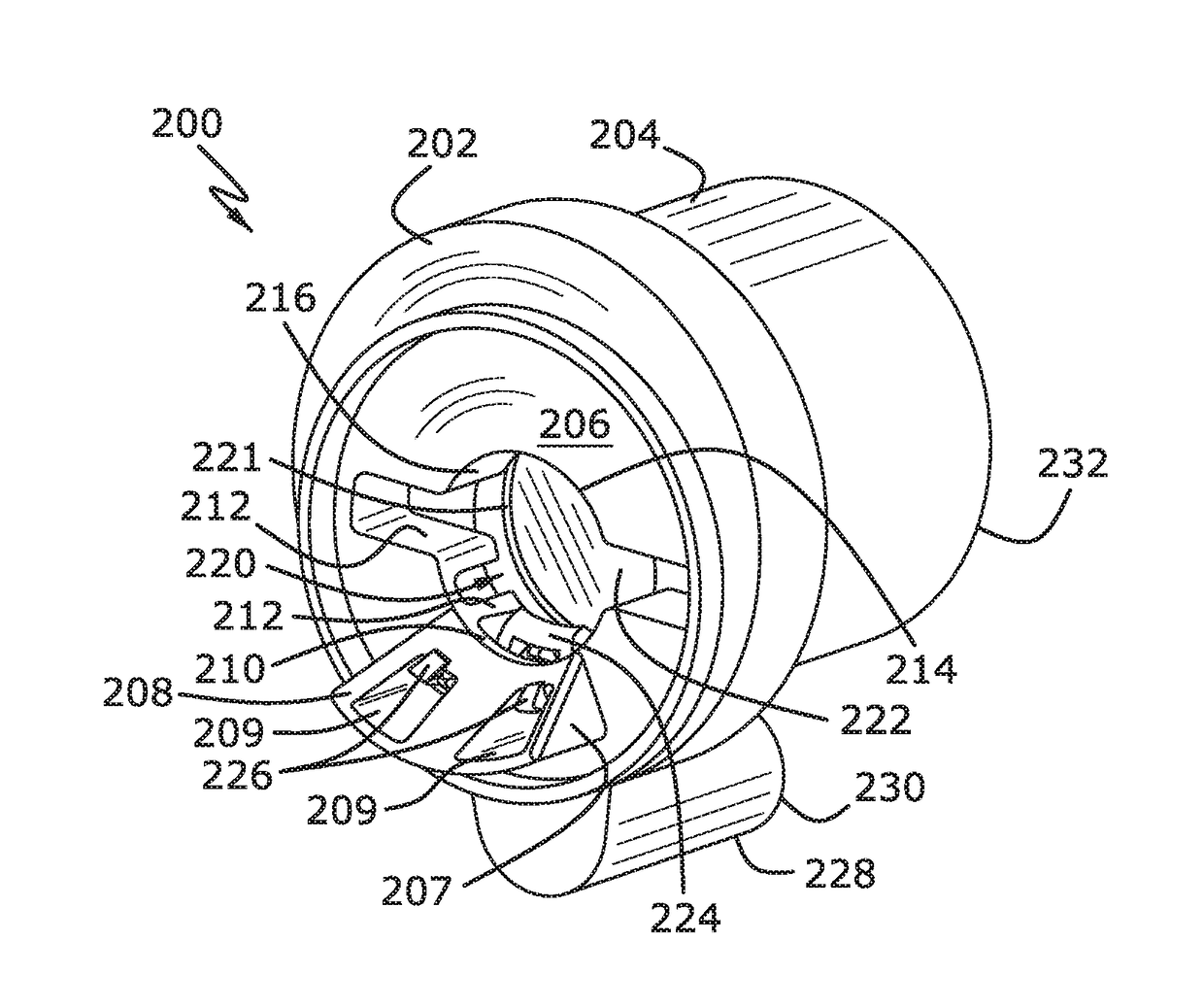
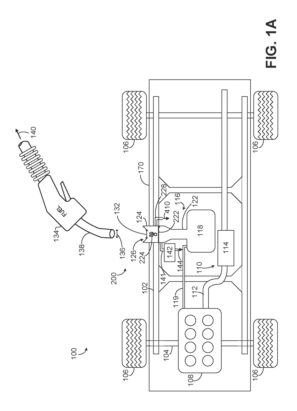
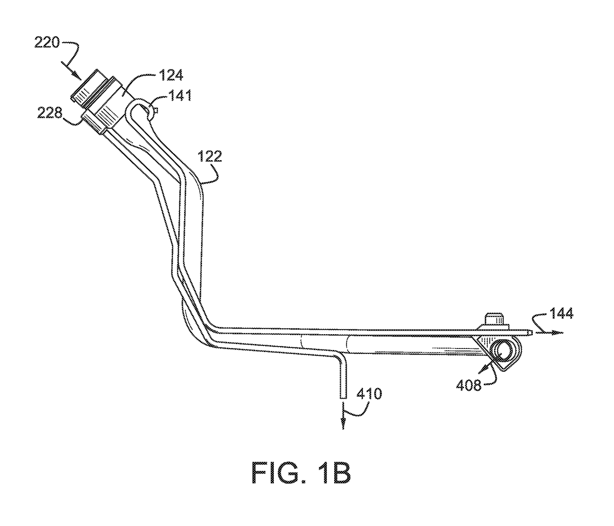
[0020]The following description relates to a capless refueling port of a vehicle, such as the vehicle shown at FIG. 1A. Details of a fueling system showing position of a drain tube and recirculation line attached to the fuel port are disclosed at FIG. 1B. For example, a capless refueling port may be included in a vehicle fueled with diesel, petrol or a suitable fuel blend such as a gasoline-ethanol fuel blend, etc. As shown at FIG. 2, the capless fuel port may be configured with a fuel nozzle opening, an articulating plug and a drain tube. The articulating plug may be adjusted to partially close a drain tube inlet of a drain tube that leads (directly or indirectly) to atmosphere in order to minimize air leakage from the atmosphere to an underground fuel storage tank during refueling. An exploded view of the capless refueling port depicting various components of the fuel port is shown at FIG. 3. The refueling port comprises a external ramped opening element adapted to fit over a fill...


PUM


Abstract

A capless refueling port attached to a fuel tank of a vehicle is presented. In one example, the capless refueling port includes a main opening, an articulating unitary plug mounted within a nozzle chamber of the fuel port, and a drain tube. The articulating plug is configured to partially or fully close an inlet of the drain tube connected to the fuel port during refueling; the articulating plug is further adjusted to open after refueling, allowing the fuel port to dissipate any residual pressure in the nozzle chamber to the atmosphere.

Description

FIELD[0001]The present description relates generally to systems of a vehicle capless refueling port. Specifically, a capless fueling port configured to reduce pressure build up in an underground fuel storage tank while minimizing fuel vapor emissions and fuel degradation.BACKGROUND AND SUMMARY[0002]Fuel systems for engines, e.g., diesel or gasoline engines, may include capless fuel port on a fuel filler pipe coupled to a fuel tank for replenishing fuel in the tank. Such a capless fueling port may include a fuel valve or sealing door which remains closed to seal off fuel system and reduce fuel vapor emissions from the fuel tank to the external atmosphere. The fuel valve or sealing door on the capless fuel port may be opened by inserting a fuel nozzle into the fuel port during refueling. Furthermore, the capless fueling port may be designed to collect and drain residual fuel and contaminants left in the fuel port after the fuel nozzle is removed at the end of refueling.[0003]An exampl...

Claims


Application Information

Patent Timeline
Patent Type & Authority Applications(United States)
IPC IPC(8): B60K15/04
CPCB60K2015/0429B60K15/0406B60K15/04B60K15/03504B60K2015/0458
Inventor ZITKOVIC, JR., MICHAEL TERRENCESONG, XIANKAI
Owner FORD GLOBAL TECH LLC
Why Eureka
Try Eureka