Slide bolt locking systems

a technology of sliding bolts and locking systems, applied in the field of sliding bolt locking systems, can solve the problems of limited adaptability, difficulty in operation, and susceptibility to dir

Inactive Publication Date: 2005-06-14
HUDSON JOHN H
View PDF13 Cites 40 Cited by
  • Summary
  • Abstract
  • Description
  • Claims
  • Application Information

AI Technical Summary

Problems solved by technology

Several problems are often associated with such lock assemblies.
Examples are difficulty in installation in a door, limited adaptability to different types of doors and

Method used


Image

  • Slide bolt locking systems
  • Slide bolt locking systems
  • Slide bolt locking systems

Examples


Embodiment Construction

[0033]For the purposes of promoting an understanding of the principles of the invention, reference will now be made to the embodiments illustrated in the drawings and specific language will be used to describe the same. It will nevertheless be understood that no limitation of the scope of the invention is thereby intended, such alterations and further modifications in the illustrated device, and such further applications of the principles of the invention as illustrated therein being contemplated as would normally occur to one skilled in the art to which the invention relates.

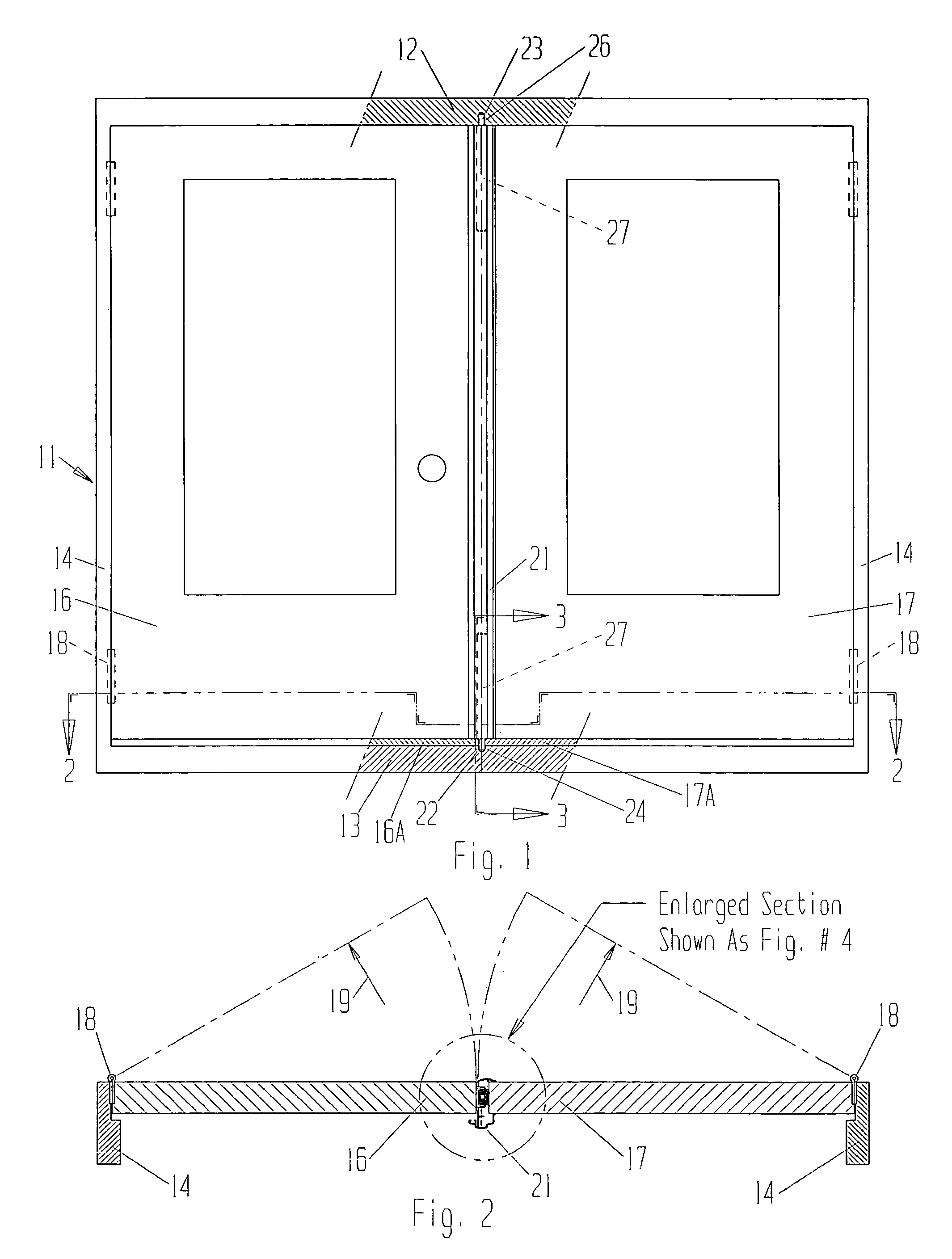
[0034]Referring now to the drawings in detail, a doorway 11 having header 12, sill 13 and jambs 14 receives two doors 16 and 17 hinged at the jambs with hinges 18 such that they swing inward in the direction of arrows 19. As will be seen, the invention is applicable to out-swinging doors as well as in-swinging doors. In the present example, with the in-swinging doors, the active door is 16 having the usual bott...


PUM


Abstract

A slide bolt type of closure locking system is disclosed in various configurations in various orientations. A lever arm is used to operate the bolt slide. A detent arrangement normally keeps the lever arm in a nested rest position. The arm can be released from the detent to pivot the arm outward to operate the bolt slide. A pivot blocker is operable to prevent folding of the arm from its outward posture when needed to operate the bolt slide. Various lock case configurations are adapted to embedded or socket-mounting, or channel mounting, or surface mounting installations in swinging, sliding or folding closures.

Description

BACKGROUND OF THE INVENTION[0001]1. Field of the Invention[0002]The present invention relates generally to locks, and more particularly to the type of lock including one part mounted on a door or a window and another part mounted in a member in the frame of a door or window opening, with a bolt in one member slidable into the other member to lock the door or window closed.[0003]2. Description of Prior Art[0004]Typical installations of French doors in a building include two swinging doors hinged at the door jambs to swing inwardly toward the interior of the building. Usually one door is kept closed and may be referred to as a “passive” door, while the other door is used most frequently and can be referred to as the “active” door. To keep the passive door closed, sliding bolt locks are used at the top and bottom of the swinging edge of the door. The bolt in the lock at the bottom of the door is receivable in a socket in the threshold of the doorway, and the bolt of the lock at the upp...

Claims


Application Information

Patent Timeline
IPC IPC(8): E05C1/00E05C1/06E05C7/04E05C7/00
CPCE05C1/065Y10S292/21Y10S292/15E05C7/045Y10T292/102
Inventor HUDSON, JOHN H.
Owner HUDSON JOHN H
Why Eureka
Try Eureka