Spherical motor using oscillatory magnetic fields

a magnetic field and oscillatory technology, applied in the direction of mechanical energy handling, magnetic circuit rotating parts, magnetic circuit shape/form/construction, etc., can solve the problems of large and complex system, sometimes unsuitable for certain applications, difficult implementation, impracticality and cost prohibitive,

Inactive Publication Date: 2005-06-14
NORTHROP GRUMMAN SYST CORP
View PDF11 Cites 22 Cited by
  • Summary
  • Abstract
  • Description
  • Claims
  • Application Information

AI Technical Summary

Problems solved by technology

Such gimbal assemblies typically employ complex wrist and elbow joints that result in a relatively large and complex system sometimes unsuitable for certain applications.
However, current spherical motor designs typically use extremely complex algorithms and modeling techniques that make their implementation difficult, impractical and cost prohibitive.

Method used


Image

  • Spherical motor using oscillatory magnetic fields
  • Spherical motor using oscillatory magnetic fields
  • Spherical motor using oscillatory magnetic fields

Examples


Embodiment Construction

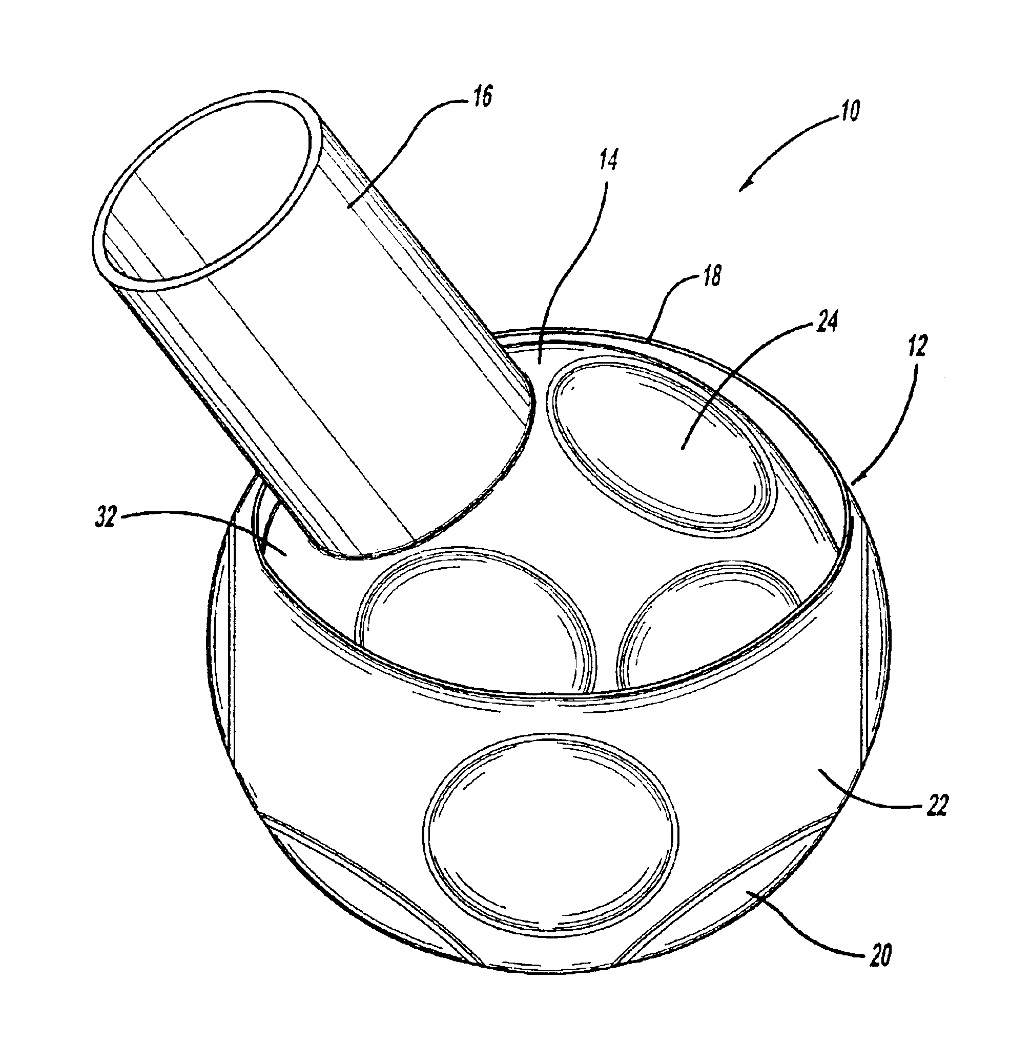
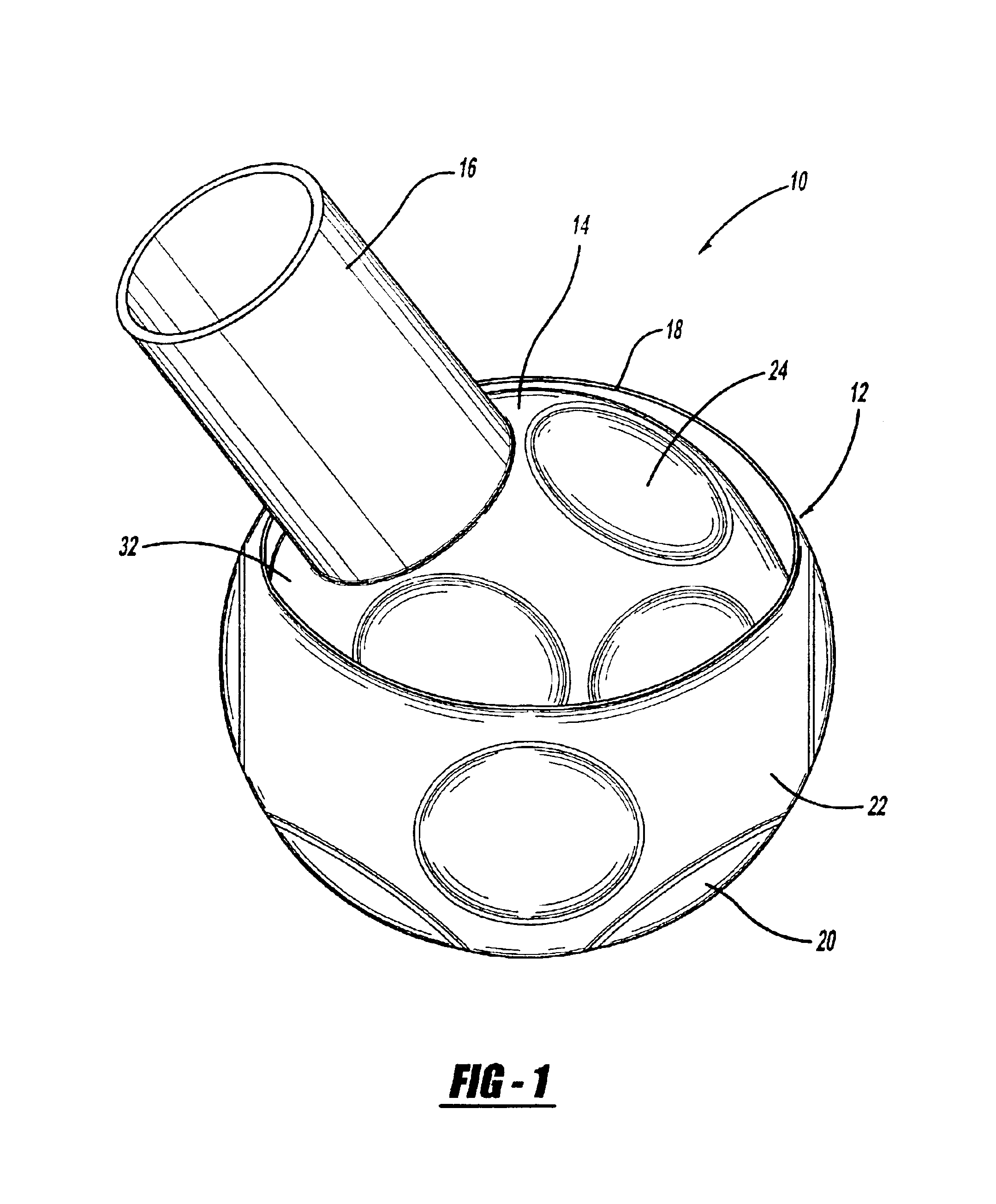
[0017]The following discussion of the embodiments of the invention directed to a spherical motor is merely exemplary in nature, and is in no way intended to limit the invention or its applications or uses.

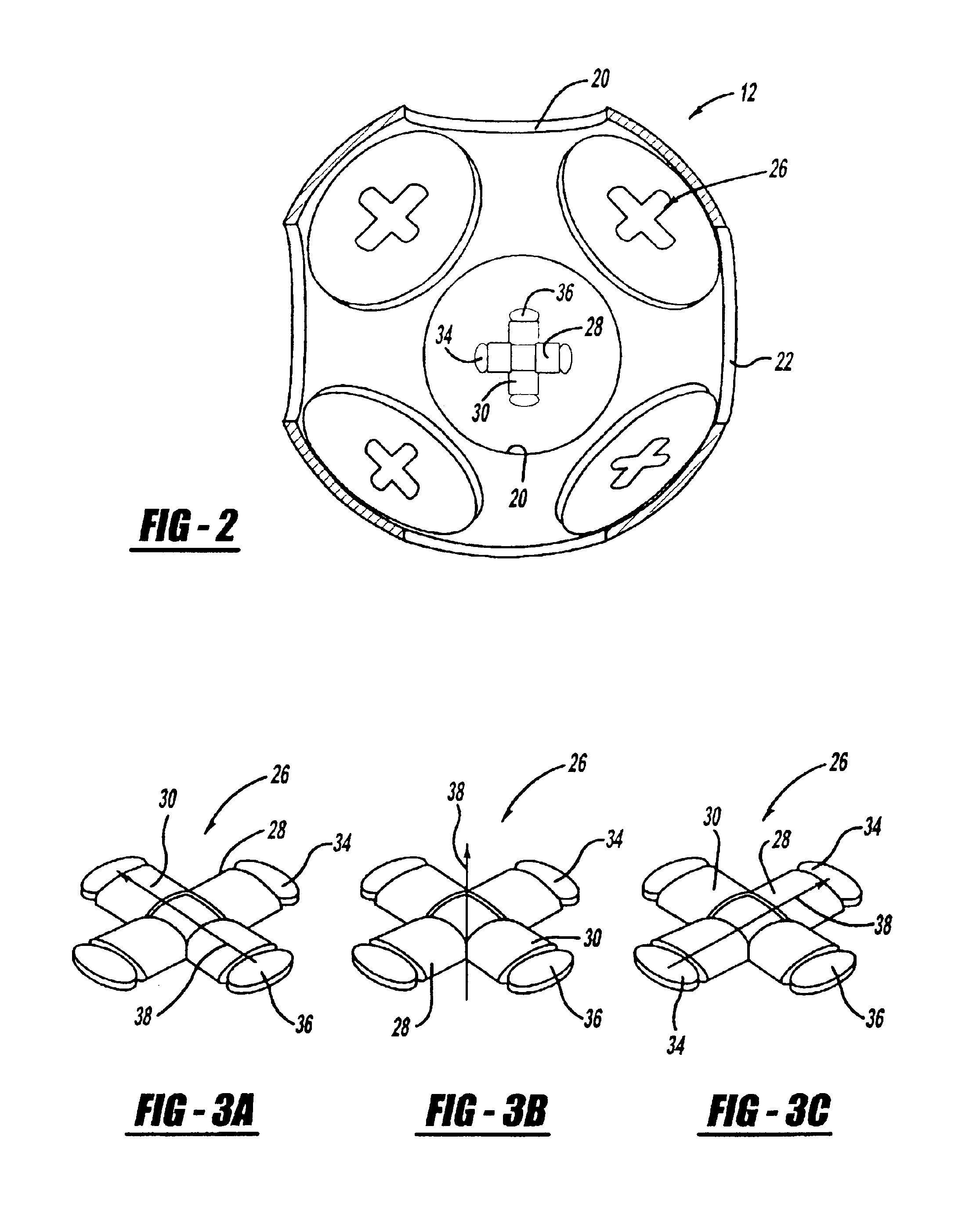
[0018]The present invention includes a spherical motor that provides three-degrees of freedom of rotation, but does not suffer the complexities of the spherical motors known in the art. As will be discussed in detail below, the spherical motor of the invention employs a plurality of field magnets that create oscillating magnetic fields that generate a voltage that is proportional to the derivative of the magnetic fields. Sensor / actuator magnets sense these oscillating magnetic fields over one complete oscillating magnetic field cycle. The sensor / actuator magnets then generate actuating magnetic fields that provide torque on the moving sphere of the motor to position it at the desired location. Thus, the motor does not need to employ a complex vision system that determines the posit...


PUM


Abstract

A spherical motor (10) that includes an outer field sphere (12) and an inner armature sphere (14) rotatable therein. Field magnetic elements (26) are disposed on the field sphere (12) and sensor / actuator magnetic elements (42) are disposed on the armature sphere (14). The field magnetic elements (26) include two coils (28, 30) providing regularly varying magnetic fields in two axes. The sensor / actuator magnetic elements (42) include coils (44-54) providing magnetic fields in three axes. Each sensor magnetic element (42) senses its localized magnetic field variations and generates a torque relative thereto. Over one complete field variation of the field magnetic elements (26), each sensor magnetic element (42) can produce torque about all three axes.

Description

BACKGROUND OF THE INVENTION[0001]1. Field of the Invention[0002]This invention relates generally to a spherical motor and, more particularly, to a spherical motor that includes a plurality of two-axis magnetic elements positioned on one of a field sphere or an armature sphere and a plurality of three-axis magnetic elements positioned on the other of the field sphere or the armature sphere, where the two-axis magnetic elements generate oscillating magnetic fields and the three-axis magnetic elements detect the oscillating magnetic fields and then provide an actuating magnetic torque to position the armature sphere.[0003]2. Discussion of the Related Art[0004]There is a need to accurately point various devices, such as antennas, sensors, detectors, etc., in a particular direction within a desired field of view. Currently, these devices are typically mounted on a two or three axis gimbal assembly where each axis includes a separate gimbal that is controlled by a separate motor to point ...

Claims


Application Information

Patent Timeline
Patent Type & Authority Patents(United States)
IPC IPC(8): H02K41/03H02K29/06H02K29/08H02K33/00
CPCH02K41/03H02K29/08H02K2201/18
Inventor MENDENHALL, TODD L.
Owner NORTHROP GRUMMAN SYST CORP
Why Eureka
Try Eureka