Pyrotechnic side impact inflator
- Summary
- Abstract
- Description
- Claims
- Application Information
AI Technical Summary
Benefits of technology
Problems solved by technology
Method used
Image
Examples
Embodiment Construction
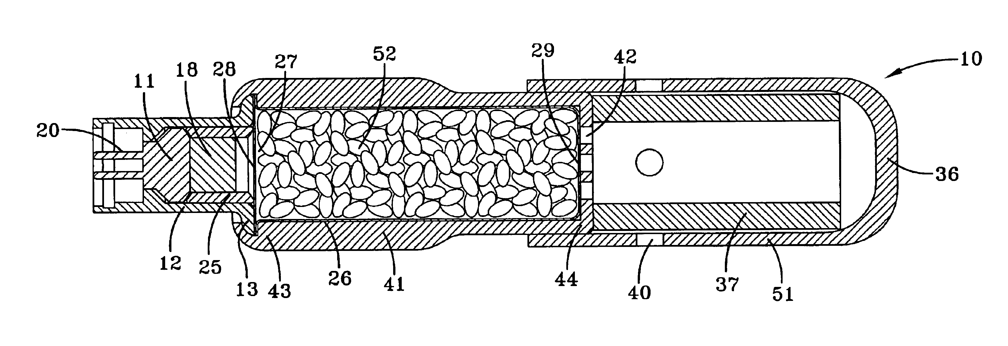
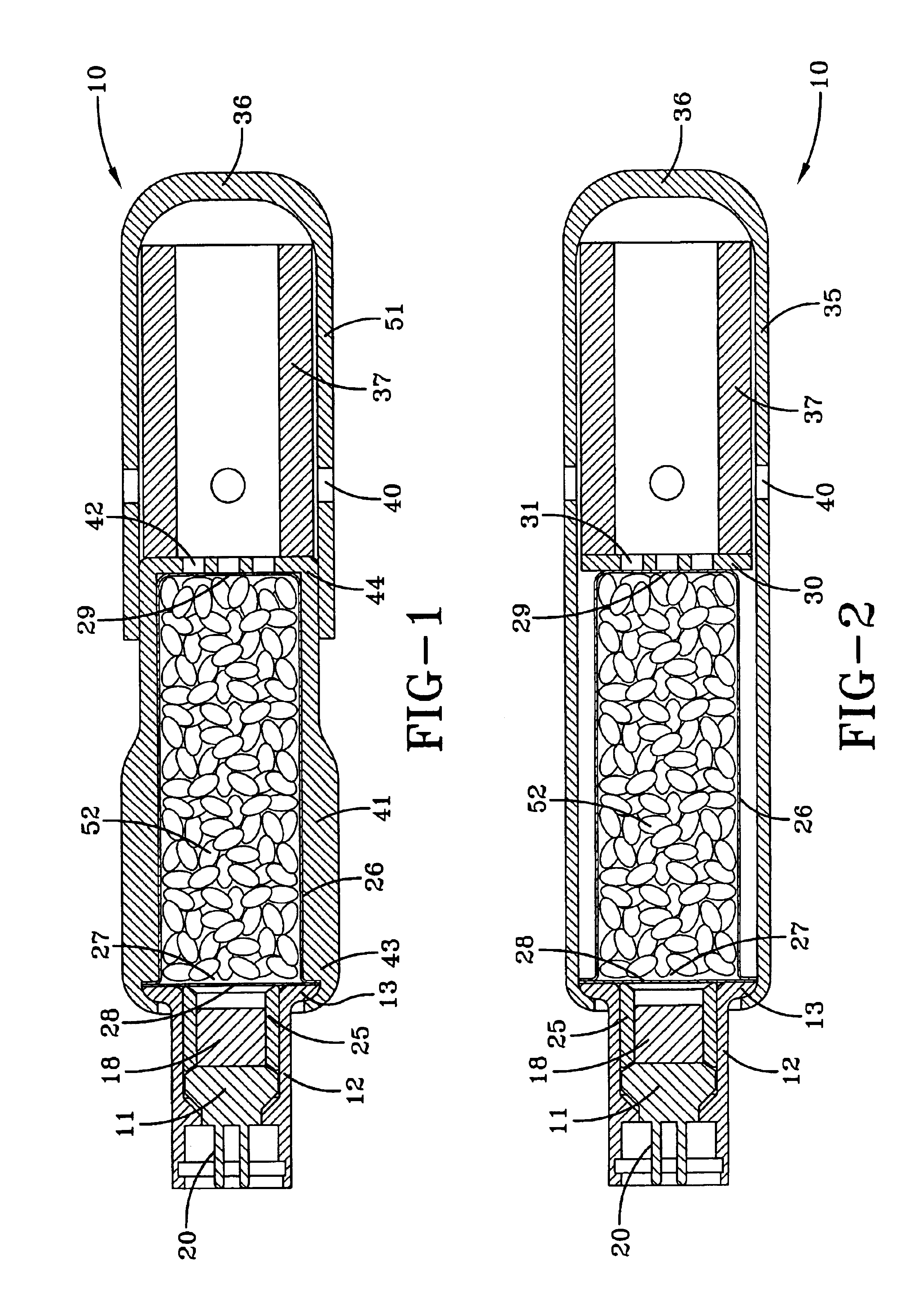
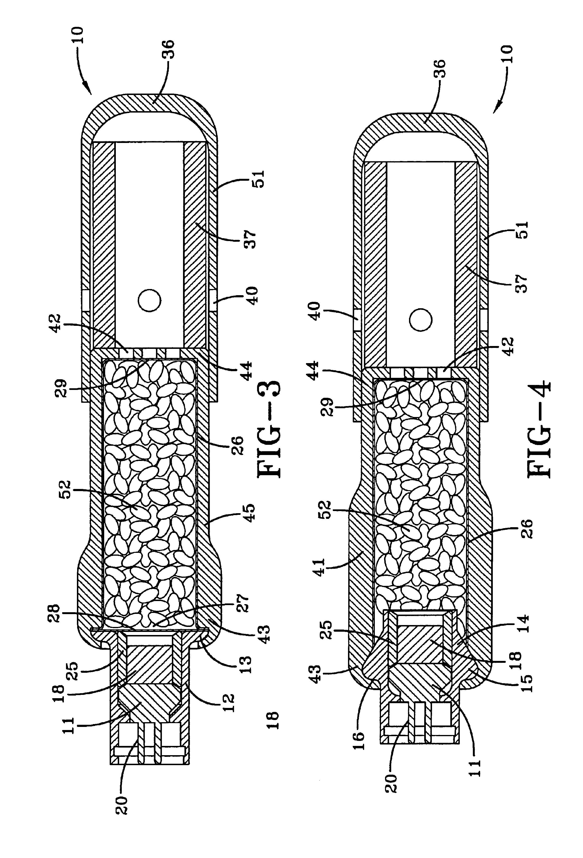
[0016]With reference to FIG. 1, a cross sectional view of a cylindrically shaped side impact inflator 10 is shown. The inflator 10 has an electrical igniter 11 for igniting the gas generant 52. The electrical igniter 11 is operatively connected to an electronic control unit (not shown). The electronic control unit receives electrical signals from crash and / or vehicle occupant sensors. The crash sensors measure deceleration while the vehicle occupant sensors measure occupant size and occupant position relative to the folded airbag. The electronic control unit processes the signals by running algorithms to determine if a side airbag (not shown) should be deployed. If the electronic control unit determines that the side airbag is necessary, then the electronic control unit sends a firing signal to the side impact inflator 10 causing the side impact inflator 10 to release inflation gas into the side airbag.
[0017]The side impact inflator 10 is deployed when the igniter 11 receives a firi...
PUM
 Abstract
Description
Claims
Application Information
 - R&D
- Intellectual Property
- Life Sciences
- Materials
- Tech Scout
- Unparalleled Data Quality
- Higher Quality Content
- 60% Fewer Hallucinations
Browse by: Latest US Patents, China's latest patents, Technical Efficacy Thesaurus, Application Domain, Technology Topic, Popular Technical Reports.
© 2025 PatSnap. All rights reserved.Legal|Privacy policy|Modern Slavery Act Transparency Statement|Sitemap|About US| Contact US: help@patsnap.com


