Rotating pneumatic knee joint structure

a knee joint and pneumatic technology, applied in the field of knee joint structure, can solve the problems of pain in the rear section of the muscle, and the inability of conventional artificial knee joint structure to be adjusted to withstand the weight of the user,

Inactive Publication Date: 2005-06-28
CHENG CHIA PAO
View PDF18 Cites 10 Cited by
  • Summary
  • Abstract
  • Description
  • Claims
  • Application Information

AI Technical Summary

Benefits of technology

[0006]Yet another object of the present invention is to provide rotating pneumatic knee joint structure, wherein the structure allows a disabled person to walk normally and naturally.

Problems solved by technology

Conventional artificial knee joint structure can only provide bending and kneeing action and when waling on uneven ground, due to the weigh of the user exerted onto the knee joint structure, the thigh will withstand different pressure and an outward pulling force will form at the sleeve, and the thigh will swing outward and twisting.
This will cause pain to the muscle at the rear section.
In other words, conventional artificial knee joint structure cannot be adjusted to withstand the weight of the user and the various type of road surface.

Method used


Image

  • Rotating pneumatic knee joint structure
  • Rotating pneumatic knee joint structure
  • Rotating pneumatic knee joint structure

Examples


Embodiment Construction

[0015]The following descriptions are of exemplary embodiments only, and are not intended to limit the scope, applicability or configuration of the invention in any way. Rather, the following description provides a convenient illustration for implementing exemplary embodiments of the invention. Various changes to the described embodiments may be made in the function and arrangement of the elements described without departing from the scope of the invention as set forth in the appended claims.

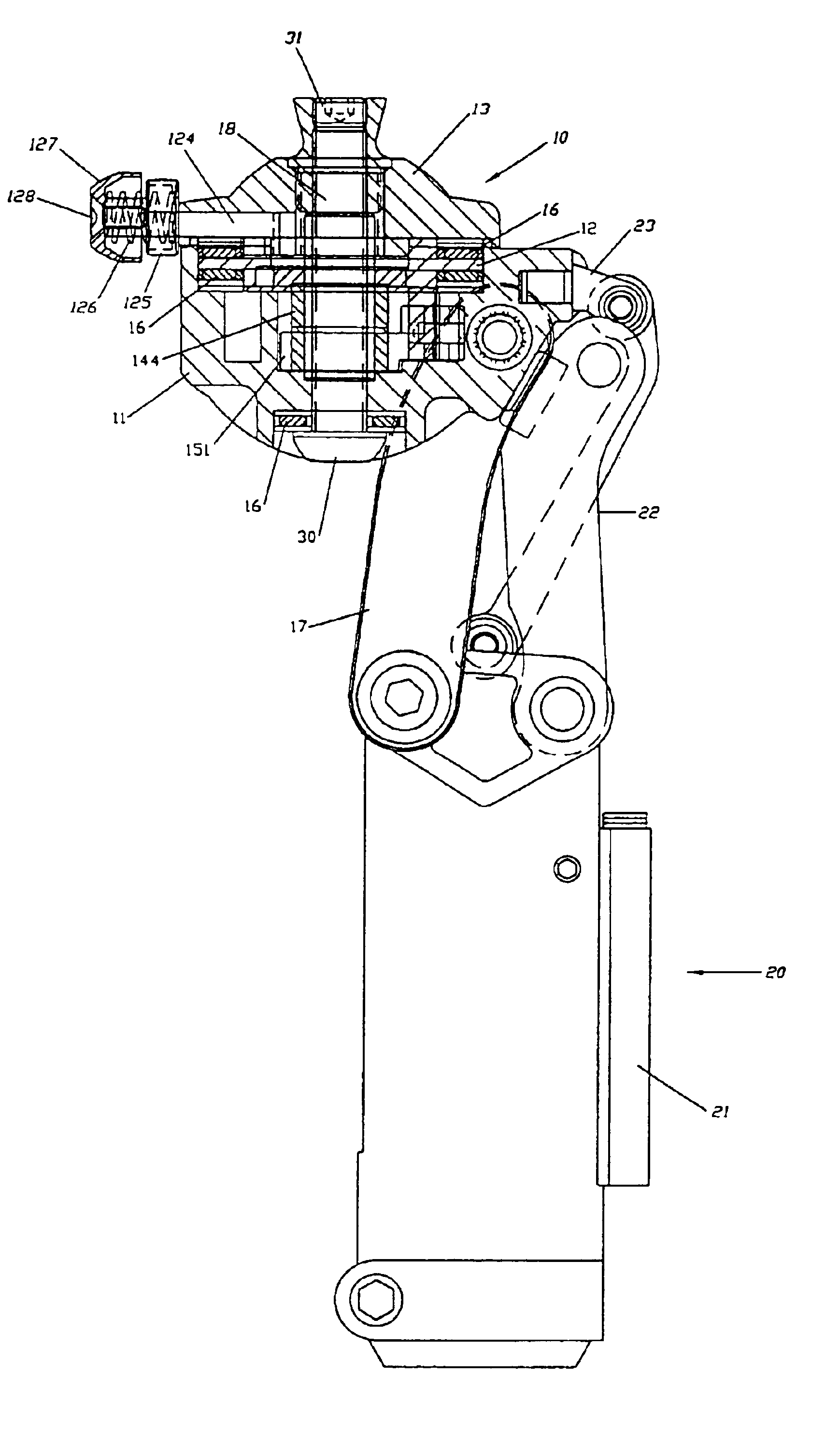
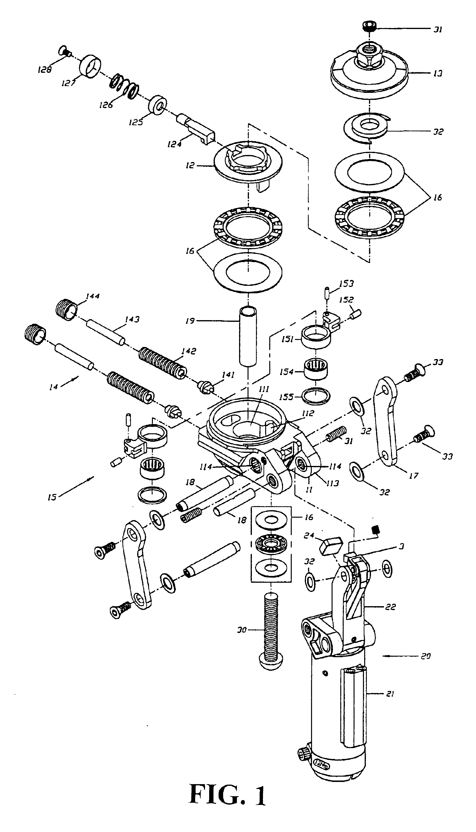
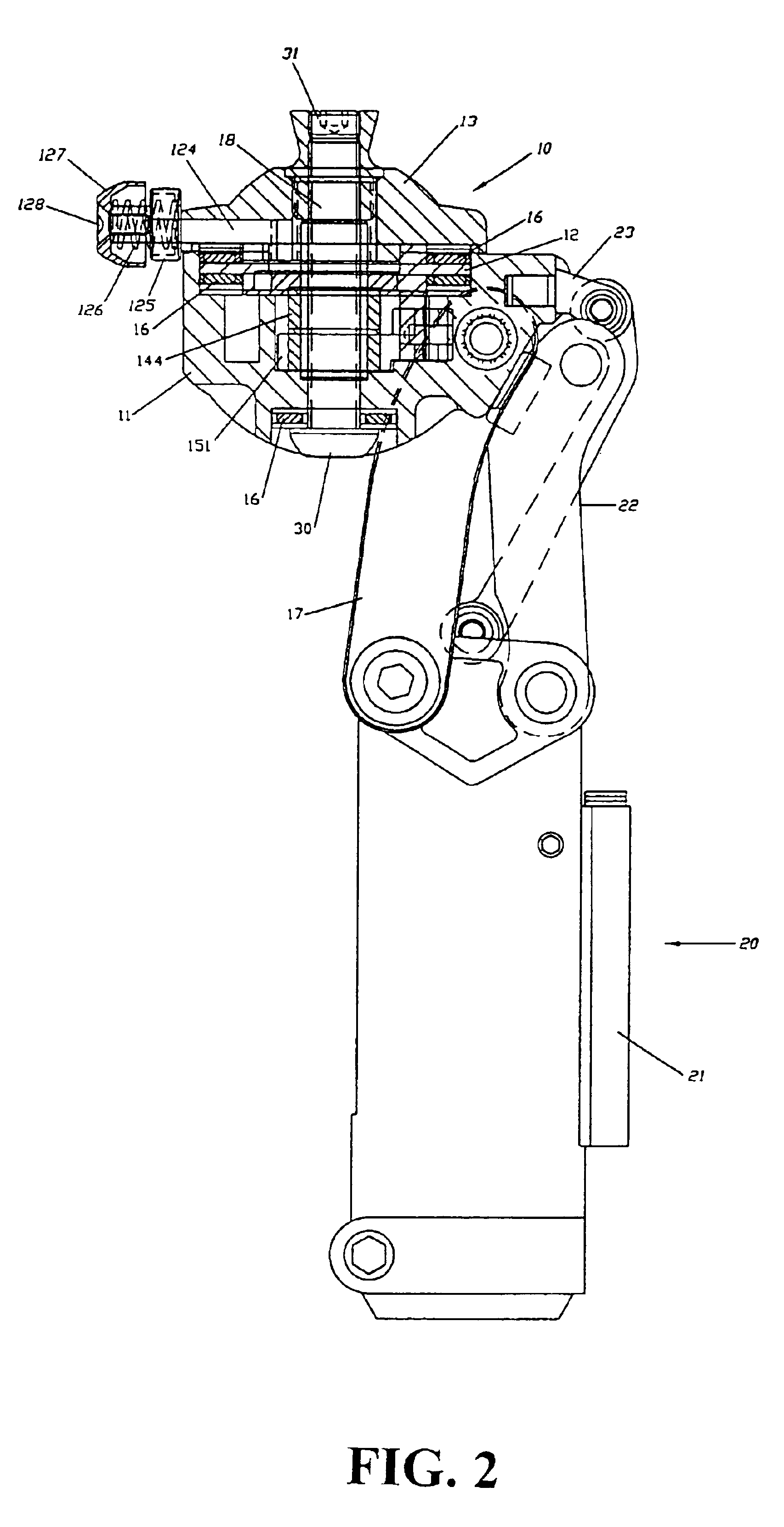
[0016]Referring to FIGS. 1 to 4A and 4B, there is shown a rotating pneumatic knee joint structure comprising a twisting connector module 10 and a pneumatic body module 20. The twisting connector module 20 includes a twisting connector 11, a rotating seat 12, an adjustable rotating upper seat 13, adjustable screws module 14 including spring support 141, spring 142, spring leaf 143 and adjustable screws 144, two rotating block modules 15 including a rotating block 151, a spring block 152, an axle 1...


PUM


Abstract

A rotating pneumatic knee joint structure is disclosed. The structure comprises a twisting connector module and a pneumatic module. The twisting connector module includes a rotating seat, an adjustable upper seat, adjustable screws, two rotating block modules, bearings, side-arch plate and axle, and screws and a plurality are used to lock all the components of the structure. A socket seat mounted at the thigh and a stop block within the rotating seat cause the lower limb connected to the pneumatic module to swing in a circular direction. Though the adjustable screw, and the spring support to hold the rotating block, the sole of the legs can be swing in a left or right direction so as to hold the weight of the user.

Description

BACKGROUND OF THE INVENTION[0001](a) Technical Field of the Invention[0002]The present invention relates to knee joint structure, and in particular, to a knee joint structure mounted to the amputated region of the thigh. The knee joint structure is provided with twisting and rotating device allowing the disabled to walk normally and naturally.[0003](b) Description of the Prior Art[0004]Conventional artificial knee joint structure can only provide bending and kneeing action and when waling on uneven ground, due to the weigh of the user exerted onto the knee joint structure, the thigh will withstand different pressure and an outward pulling force will form at the sleeve, and the thigh will swing outward and twisting. This will cause pain to the muscle at the rear section. In other words, conventional artificial knee joint structure cannot be adjusted to withstand the weight of the user and the various type of road surface. Accordingly, it is an object of the present invention to provi...

Claims


Application Information

Patent Timeline
Patent Type & Authority Patents(United States)
IPC IPC(8): A61F2/50A61F2/68A61F2/60A61F2/64A61F2/00A61F2/74
CPCA61F2/644A61F2/68A61F2002/30359A61F2002/5003A61F2220/0033A61F2002/5075A61F2002/747A61F2002/748A61F2002/5041A61F2/74A61F2/748
Inventor CHENG, CHIA PAO
Owner CHENG CHIA PAO
Why Eureka
Try Eureka