Safety inlet assembly for pool drains

a technology for drains and safety inlet assemblies, which is applied in the direction of swimming pools, water/sludge/sewage treatment, chemical instruments and processes, etc., can solve the problems of traumatic and physical dangerous situations, pool users can be exposed to considerable risks, and many reported drownings a year, so as to eliminate high suction conditions and be easily and inexpensively integrated

Inactive Publication Date: 2005-07-05
VERVE
View PDF3 Cites 28 Cited by
  • Summary
  • Abstract
  • Description
  • Claims
  • Application Information

AI Technical Summary

Benefits of technology

[0005]The present invention provides a safety inlet assembly that may be readily and inexpensively incorporated into existing suction drains for pools, spas and other water circulation facilities and limits suction conditions. The safety inlet assembly is adapted for use with existing main and skimmer drain designs, requiring only conventional couplings. The inlet assembly comprises a domed perforated tube having a lower mounting collar that attached with the coupling to the drain inlets. The drain cover is attached to the tube. Should the cover become dislodged, the tube provides a three dimensional hole array that eliminate high suction conditions even if the hole pattern is partially obstructed. The inlet assembly in one embodiment utilizes telescoping tubes providing protective redundancy in the event a tube and associated cover are dislodged.
[0006]Accordingly, it is an object of the present invention to provide a flow control device for swimming pool suction drains that may be inexpensively and readily installed into existing pools.
[0008]A further object of the invention is to provide a drain safety device that can be adapted to existing pool installations using easy to obtain components.

Problems solved by technology

It is now recognized that such drain conditions can pose considerable risks to pool users, particularly children.
The drain conditions can entrap swimmers, resulting in numerous reported annual drownings as a result of an inability to break free of the extreme suction condition.
Hair and apparel may also be entangled in the drain, resulting in traumatic and physically dangerous situations.
During use, however, the covers and openings may become dislodged and the protective features are lost.
Accordingly, even the currently proposed circulation conditions do not entirely overcome acute suction conditions at the drain inlet.
The economics of retrofit have limited the use of these approaches in existing pool installations where the governmental control is not applicable.

Method used


Image

  • Safety inlet assembly for pool drains
  • Safety inlet assembly for pool drains
  • Safety inlet assembly for pool drains

Examples


Embodiment Construction

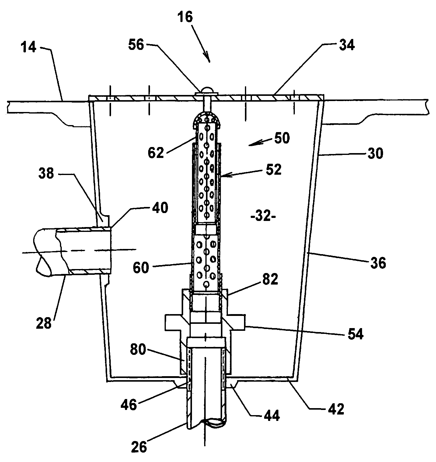
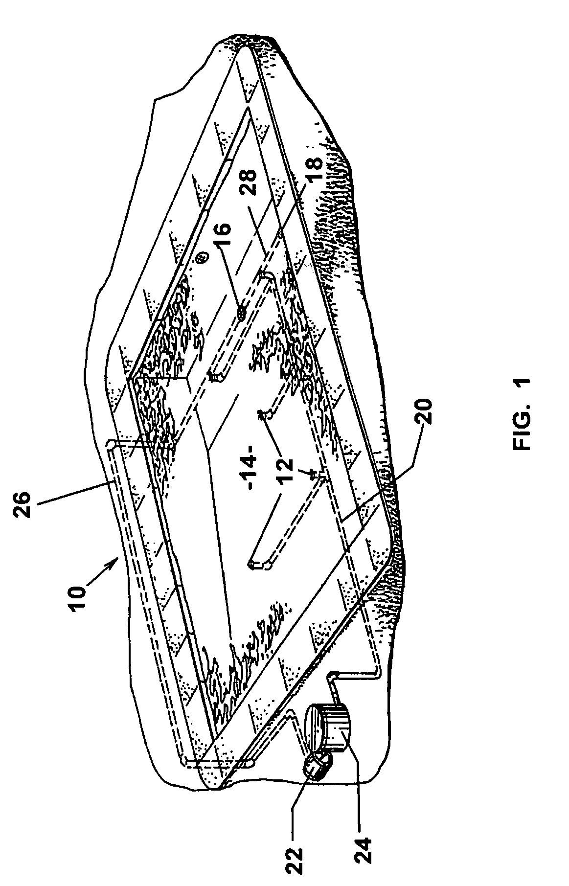
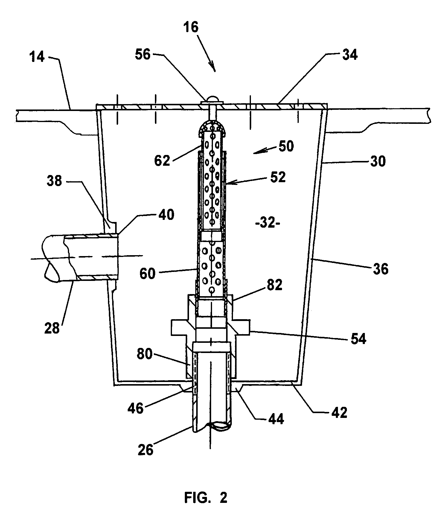
[0016]Referring to the drawings for the purpose of illustrating a preferred embodiment of the invention and not for limiting same, FIG. 1 shows a swimming pool 10 having a plurality of water supply outlets 12 around the base 14 for circulating water to the pool, and a main drain 16 and a skimmer drain 18 for returning water from the pool 10.

[0017]The outlets 12 are serially connected by an outlet conduit 20 in a supply line from a pump 22 and a filter 24. The main drain 16 is connected by main conduit 26 in a return line to the pump 22. The skimmer drain 18 is connected with the main drain 16 by branch conduit 28. Conventionally the main drain 16 is located at the deepest portion of the pool and centrally thereof. The skimmer drain 18 may be deployed in varying modes. The skimmer drain may be integrated into the sidewalls of the pool for straining upper level debris. The skimmer drain may also be employed as a floating device and coupled to the branch conduit by a flexible hose. In ...


PUM


Abstract

A safety inlet drain assembly for main and skimmer drains of a swimming pool includes a perforated cylinder in the drain cavity mounted at a lower end on the drain return line and having a domed cap on the upper end to which the drain gate cover is attached by fasteners. The safety drain assembly is configured for precluding complete blockage by pool users in the event of displacement of the cover plate thereby preventing excessive suction conditions otherwise posing physical danger to the users.

Description

FIELD OF THE INVENTION[0001]The present invention relates to pool drains, and, in particular, to main and skimmer drains for swimming, wading, and circulating pools incorporating safety devices for preventing inadvertent blockage by pool users.BACKGROUND OF THE INVENTION[0002]Swimming and wading pools, as well as certain spas, are equipped with powerful water circulation filtration systems. Such pools use one or more drains in the pump return line that generate high flow, high suction conditions at their inlets. It is now recognized that such drain conditions can pose considerable risks to pool users, particularly children. The drain conditions can entrap swimmers, resulting in numerous reported annual drownings as a result of an inability to break free of the extreme suction condition. Hair and apparel may also be entangled in the drain, resulting in traumatic and physically dangerous situations. Disembowelments have also been reported.[0003]As a result of these repetitive accident...

Claims


Application Information

Patent Timeline
Patent Type & Authority Patents(United States)
IPC IPC(8): E04H4/12E04H4/00
CPCE04H4/1236
Inventor NOWELL, RICHARD
Owner VERVE
Why Eureka
Try Eureka