Multi-channel retaining wall block and system

a technology of retaining wall and multi-channel, applied in the field of retaining wall blocks and retaining walls, can solve the problems of multiple inventory items, cost and inefficiency of using multiple molds, and inefficient from a production standpoint, and achieve the effect of improving production efficiency, reducing production costs, and improving production efficiency

Inactive Publication Date: 2005-07-05
KEYSTONE RETAINING WALL SYST
View PDF38 Cites 99 Cited by
  • Summary
  • Abstract
  • Description
  • Claims
  • Application Information

AI Technical Summary

Benefits of technology

[0010]This invention is a block system comprising multiple sizes and shapes of blocks with differently dimensioned, interchangeable front and back faces. The blocks can be used to construct an eye-pleasing, irregularly textured wall having a weathered, natural appearance. The texture of the wall is due to the variation in the size of the blocks, the weathered, natural appearance on the surfaces of the individual blocks, and the placement of the blocks in the wall. The shape of the blocks permits construction of stable walls that are curved or straight as well as providing for walls having 90 degree corners.

Problems solved by technology

However, the creation of a truly random appearance requires the production of multiple block shapes for use in a single retaining wall.
This is inefficient from a production standpoint because this requires multiple molds and more kinds of blocks to inventory.
If only one face of the block is intended to be the front face, then the block system will suffer a trade-off between having enough face sizes to create a random, natural appearance and the cost and inefficiency of using multiple molds and creating multiple inventory items.
However, problems still remain in the field of retaining walls.

Method used


Image

  • Multi-channel retaining wall block and system
  • Multi-channel retaining wall block and system
  • Multi-channel retaining wall block and system

Examples


second embodiment

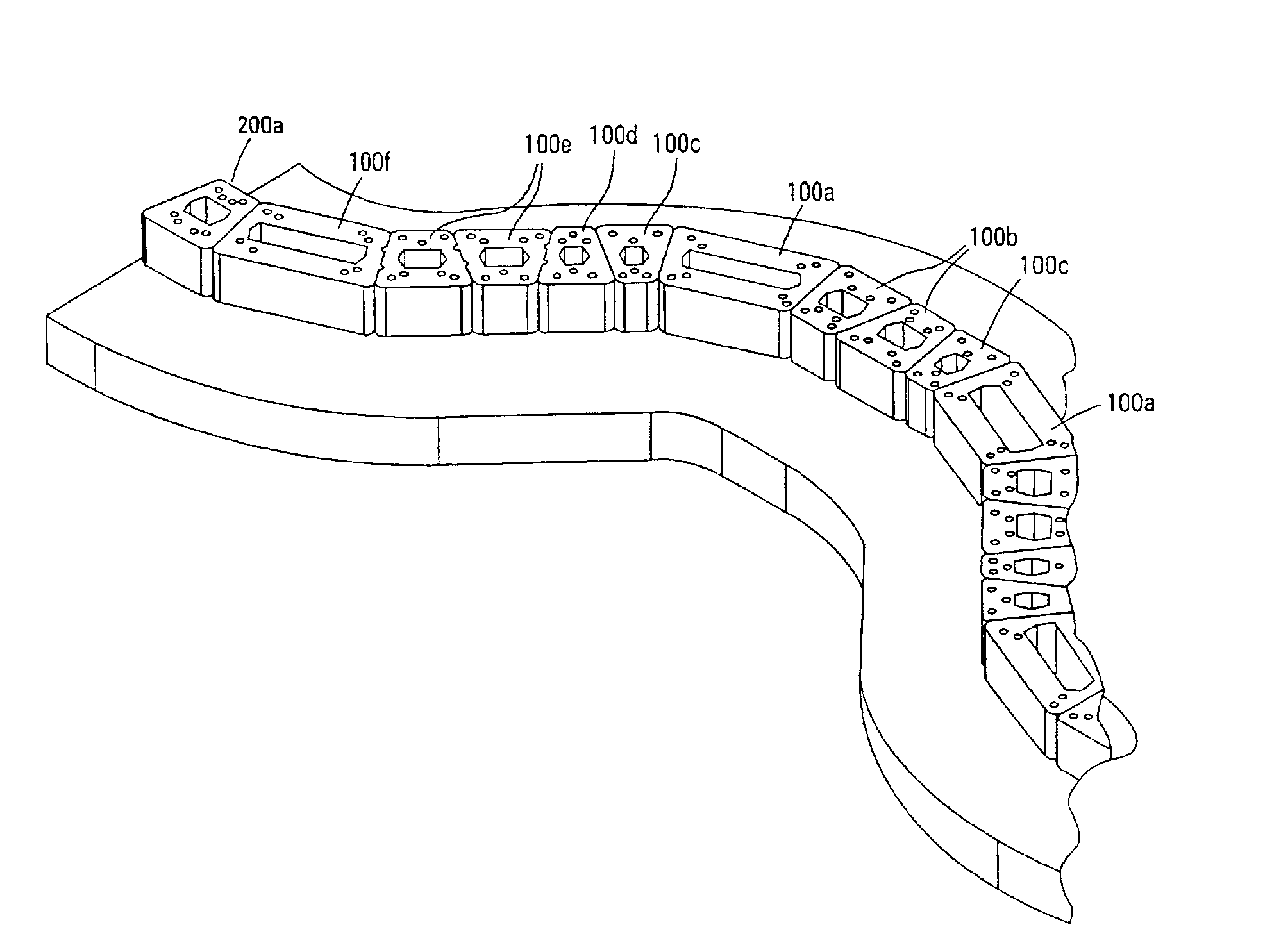
[0049]The second embodiment is shown in FIGS. 3A, 3B, and 4A to 4C. Again, there are blocks of three sizes and these blocks are used most often in constructing the ends or corners of a wall. FIGS. 3A and 4A show the same block and 3B and 4B show the same block. The smallest block is shown only in bottom view in FIG. 4C.

[0050]Blocks 100a and 200a are similarly dimensioned, as are blocks 100b and 200b, and 100c and 200c. In this way, the blocks can be used interchangeably and where necessary in a wall. As is well understood in the art, the blocks can be made of any desired dimension. Blocks of three sizes for each embodiment are illustrated, though it is to be understood that many different sizes could be made and used to construct a wall.

[0051]Preferably, each block of either embodiment has at least two faces that are textured in a manner resulting in the appearance of natural stone. Three of the faces may be textured, and typically it is desirable that a face that will be placed nex...

first embodiment

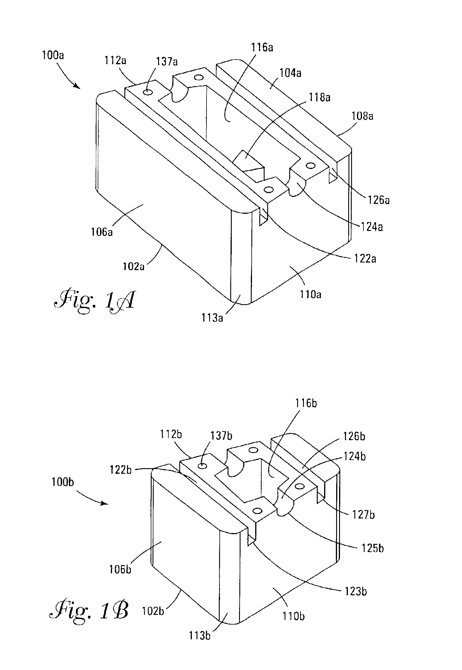
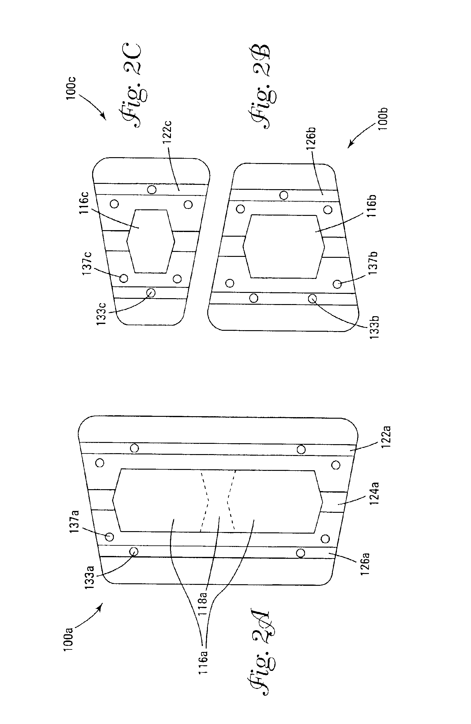
[0057]FIGS. 1 and 2 illustrate three sizes of the block of this invention. Perspective views of blocks 100a and 100b are shown in FIGS. 1A and 1B. Bottom views of blocks 100a, 100b, and 100c are shown in FIGS. 2A to 2C, respectively. The block comprises lower surface 104 opposed and substantially parallel to upper surface 102, and opposing and substantially parallel first and second (also referred to as front and back) faces 106 and 108, respectively. For the purposes of this description, front face 106 is shown facing the viewer in FIG. 1A, however, it is to be understood that front and back are interchangeable when the blocks are used in a wall. The block also comprises opposing and converging side surfaces 110 and 112 (i.e., imaginary lines coincident with side surfaces 110 and 112 will eventually converge at some distance away from the back of block 100a). The side surfaces are separated by the width of the block. The side surfaces join the front and back faces to form rounded c...


PUM


Abstract

A retaining wall block system having multiple sizes and shapes of blocks with differently dimensioned, interchangeable front and back faces. The blocks are used to construct an irregularly textured wall having a weathered, natural appearance. Multiple channels in the lower face of the block are used to engage pins in pin-receiving apertures to form an attachment system. A side connection system is particularly useful for stabilizing free-standing walls. Horizontal reinforcing members are also used in the channels and vertical reinforcing members are used in cores of adjacent blocks for reinforcing a wall. Reinforcing geosynthetic materials can also be firmly held in a wall by means of the pins or by connectors adapted to fit in the block channels.

Description

[0001]This application is a continuation-in-part of U.S. application Ser. No. 09 / 904,038, filed Jul. 12, 2001 now U.S. Pat. No 6,854,231.FIELD OF THE INVENTION[0002]This invention relates generally to retaining wall blocks and retaining walls constructed from such blocks. In particular, this invention relates to retaining wall blocks having channels, pin receiving apertures, and cores and a wall system made from such blocks that can be reinforced horizontally as well as vertically.BACKGROUND OF THE INVENTION[0003]Retaining walls are used in various landscaping projects and are available in a wide variety of styles. Numerous methods and materials exist for the construction of retaining walls. Such methods include the use of natural stone, poured concrete, precast panels, masonry, and landscape timbers or railroad ties.[0004]In recent years, segmental concrete retaining wall units, which are dry stacked (i.e., built without the use of mortar), have become widely accepted in the constr...

Claims


Application Information

Patent Timeline
Patent Type & Authority Patents(United States)
IPC IPC(8): E02D29/02
CPCE02D29/0241E02D29/0283
Inventor MACDONALD, ROBERT A.RACE, ROBERT J.
Owner KEYSTONE RETAINING WALL SYST
Why Eureka
Try Eureka